
Heating and spinning flaring device

A technology of flaring dies and hydraulic cylinders, which is applied in the field of fork wheel hub processing devices, can solve the problems of fork wheel hub cracks, lower processing yields, and inability to obtain flare diameters, etc., to ensure service life, yield, and accuracy and the effect on the integrity of the appearance

Inactive Publication Date: 2019-02-22
YUEXI SHENGHONG IND & TRADE
View PDF8 Cites 2 Cited by
  • Summary
  • Abstract
  • Description
  • Claims
  • Application Information

AI Technical Summary

Problems solved by technology

However, the existing heating spinning flaring device mainly controls the size of the fork wheel hub flaring through the descending distance of the flaring die 4, which often leads to a large deviation between the size of the fork wheel hub flaring and the design value, and cannot independently adjust the flaring size. This will cause cracks in the processed fork wheel hub, thereby reducing the processing yield and failing to obtain a flare diameter that matches the design value.

Method used


Image

  • Heating and spinning flaring device
  • Heating and spinning flaring device
  • Heating and spinning flaring device

Examples


Embodiment 1

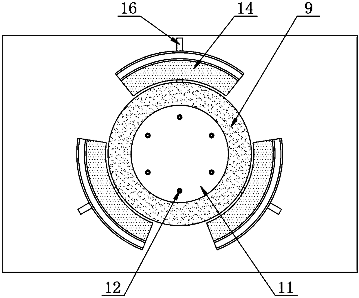
[0023] according to Figure 1-3 A heating spinning flaring device shown includes a main frame 1 and a hydraulic cylinder 2, the hydraulic cylinder 2 is arranged on the top of the main frame 1, and a movable plate 3 is provided at one end of the output shaft of the hydraulic cylinder 2, and the movable plate 3 is The bottom of the plate 3 is provided with a flaring die 4, and the outside of the flaring die 4 is provided with a positioning block 5, and the bottom end of the positioning block 5 is provided with a receiving groove 6, and the inside of the receiving groove 6 is provided with a ball 7. The bottom of the die 4 is provided with a fixed plate 8, and the top of the fixed plate 8 is provided with a movable plate 9, and the inside of the movable plate 9 is provided with a heating rod 10, and the inside of the movable plate 9 is provided with a flared mold groove 11. A first fixing bolt 12 is provided inside the flared die groove 11, a heat insulating layer 13 is provided ...

Embodiment 2

[0029] according to Figure 4 A kind of heating spinning flaring device shown, described flaring die 4 and positioning block 5 are fixedly connected with movable plate 3, and described flaring die 4 is matched with flaring die groove 11, and flaring die 4 When processing the fork wheel hub in the flared die groove 11, the opening groove at the top of the flared die groove 11 can be shaped, and prevent the flared die 4 from further penetrating into the flared die groove 11 to ensure that the processed forklift The precision of the hub and the integrity of the appearance;

[0030] The heat insulation layer 13 is fixedly connected with the outer wall of the movable plate 9, and the heat insulation layer 13 is made of rock wool material, and the heat insulation layer 13 of the rock wool material is provided to process the fork wheel hub in the flared die groove 11. The heat generated by the heating rod 10 is isolated to prevent the high temperature from being directly transmitted...


PUM


Abstract

The invention discloses a heating and spinning flaring device which comprises a main body frame and a hydraulic cylinder, wherein the hydraulic cylinder is arranged at the top of the main body frame,and a mobile plate is arranged at one end of an output shaft of the hydraulic cylinder. A flaring die is arranged at the bottom of the mobile plate, and a positioning block is arranged at the outer part of the flaring die. A storage slot is formed in the bottom end of the positioning block, and a ball is arranged in the storage slot. A fixing plate is arranged at the bottom of the flaring die, anda mobile disc is arranged at the top of the fixing plate. A heating rod is arranged in the mobile disc, and a flaring die slot is formed in the mobile disc. A first fixed slot is arranged in the flaring die slot, and a thermal insulating layer is arranged on the outer wall of the mobile disc. According to the heating and spinning flaring device, the position of a positioning disc is adjusted by asecond fixed bolt, and the relative position of the positioning disc and the positioning block is adjusted by the second fixed bolt; the hydraulic cylinder works to drive the flaring die to flare a hub of a forklift truck through the mobile plate, and the inclined plane of the positioning block is limited by the inclined plane of the positioning disc; and therefore the effect of adjusting the size of flaring is achieved.

Description

technical field [0001] The invention relates to the technical field of fork wheel hub processing devices, in particular to a heating, spinning and flaring device. Background technique [0002] Forklifts are industrial handling vehicles, which refer to various wheeled handling vehicles for loading and unloading, stacking and short-distance transportation of palletized goods. The technical parameters of forklifts are used to indicate the structural characteristics and working performance of forklifts. The main technical parameters are: rated lifting capacity, load center distance, maximum lifting height, gantry inclination, maximum driving speed, minimum turning radius, minimum ground clearance, wheel base, wheel base, etc. The forklift hub is an important structural part related to the safety of forklift driving. Its quality and reliability are not only related to the safety of the vehicle and the personnel and materials on the vehicle, but also affect the stability, maneuver...

Claims


Application Information

Patent Timeline
Patent Type & Authority Applications(China)
IPC IPC(8): B21D41/02B21D53/26B21D37/16B21D43/00
CPCB21D37/16B21D41/02B21D43/003B21D53/26
Inventor 刘振国
Owner YUEXI SHENGHONG IND & TRADE
Learn More