
Sheet metal part machining device

A processing device and technology for sheet metal parts, applied in the field of sheet metal parts processing, can solve the problems of low punching quality of sheet metal parts, achieve the effects of shortening the processing cycle, reducing the probability of burrs, and reducing labor costs

Inactive Publication Date: 2019-02-22
象山维治模具有限公司
View PDF0 Cites 7 Cited by
  • Summary
  • Abstract
  • Description
  • Claims
  • Application Information

AI Technical Summary

Problems solved by technology

[0003] The purpose of the present invention is to provide a sheet metal parts processing device to solve the problem of low punching quality of sheet metal parts in the prior art

Method used


Image

  • Sheet metal part machining device
  • Sheet metal part machining device
  • Sheet metal part machining device

Examples


Embodiment Construction

[0032] The following is further described in detail through specific implementation methods:

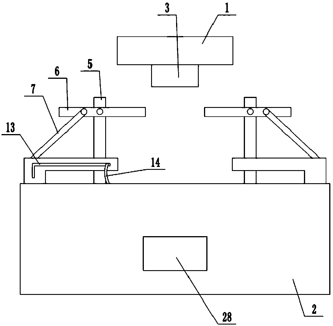
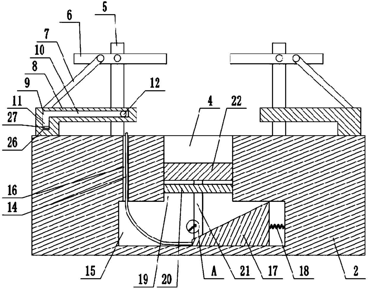
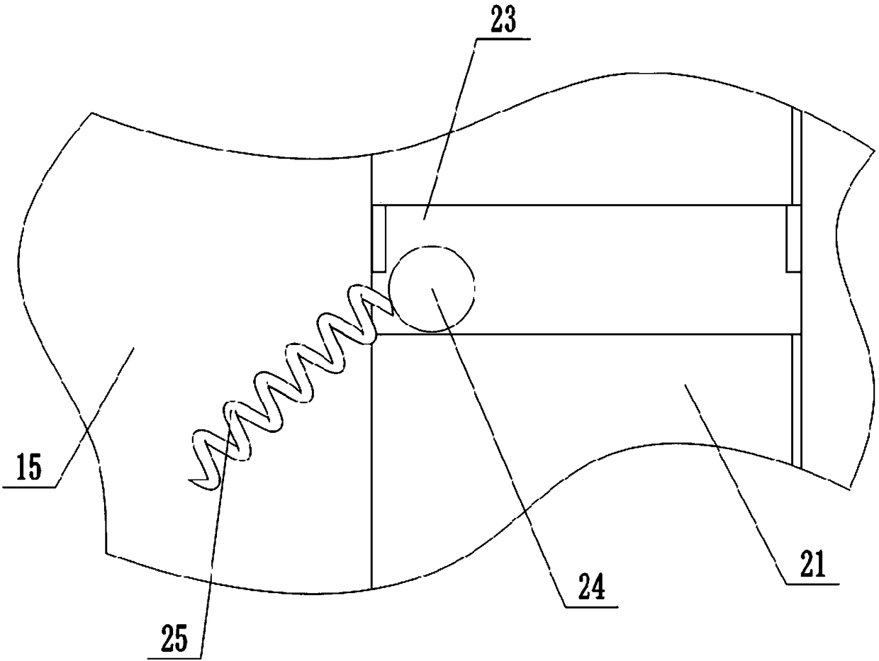
[0033] The reference signs in the drawings of the description include: upper mold 1, lower mold 2, convex part 3, concave part 4, cylinder 5, rotating rod 6, connecting rod 7, slide plate 8, chute 9, horizontal part 10, vertical part Part 11, slider 12, sliding hole 13, pull cord 14, movable cavity 15, vertical hole 16, moving plate 17, first elastic member 18, through hole 19, fixed plate 20, screw rod 21, grinding block 22, annular groove 23. Rotating bead 24, second elastic member 25, electromagnet 26, magnetic block 27, discharge port 28.

[0034] The embodiment is basically as attached figure 1 And attached figure 2 Shown:

[0035] The sheet metal parts processing device is mainly composed of an upper mold 1, a lower mold 2, a convex part 3, a concave part 4, a pressing mechanism, a grinding mechanism, and a pulling mechanism. The lower mold 2 is installed on the frame, the...


PUM


Abstract

The invention relates to the technical field of sheet metal part machining and discloses a sheet metal part machining device comprising an upper die and a lower die. The two sides of the lower die areboth provided with pressing and fixing mechanisms which are used for pressing a sheet metal part flat and fixing the sheet metal part. Each pressing and fixing mechanism comprises a column body, wherein a rotating rod is rotationally connected to the column body. One end of each rotating rod is located on the movement path of the lower die. The other end of each rotating rod is hinged to a connection rod. The side portion of the lower die is connected with sliding plates in a sliding manner. The end, far away from a concave portion, of each sliding plate is hinged to a connection rod. One sliding plate is provided with a pulling mechanism. A rotary grinding mechanism used for deburring of a punched hole is arranged in the lower die. When the sliding plate slides away from the sheet metalpart, the rotary grinding mechanism can be driven by the pulling mechanism to conduct deburring treatment on the punched hole. According to the sheet metal part machining device, the fixing work and pressing flattening work are welled conducted on the sheet metal part before punching, so that it is avoided that the sheet metal part deforms in the punching process; and the rotary grinding mechanismis adopted after punching of the sheet metal part, so that burrs generated after punching are removed, and therefore the punching quality of the sheet metal part is improved.

Description

technical field [0001] The invention belongs to the technical field of sheet metal parts processing. Background technique [0002] Sheet metal is a comprehensive cold working process for thin metal plates (usually below 6mm), including shearing, punching / cutting / compositing, folding, welding, riveting, splicing, forming (such as automobile body), etc. Its distinctive feature is the same Part thickness is consistent. Products processed by sheet metal technology are called sheet metal parts. The sheet metal parts referred to by different industries are generally different, and are mostly used for assembly. The sheet metal parts generally use thin plates for punching processing. The pulling force is large, so that the punching edge of the sheet metal part is prone to burrs, and the burrs are large. At the same time, the pulling force is also easy to deform the sheet metal part, which further increases the possibility of burrs and leads to poor punching quality of the sheet me...

Claims


Application Information

Patent Timeline
Patent Type & Authority Applications(China)
IPC IPC(8): B21D28/26B24B9/04
CPCB21D28/26B24B9/04
Inventor 毛薇薇
Owner 象山维治模具有限公司
Learn More