
Heterojunction solar cell and preparation method thereof

A solar cell and heterojunction technology, applied in the field of solar cells, can solve the problems of optical loss, narrow band gap, affecting the short-circuit current density and photoelectric conversion efficiency of the cell, etc.

Pending Publication Date: 2019-02-05
SUZHOU TALESUN SOLAR TECH CO LTD +1
View PDF0 Cites 0 Cited by
  • Summary
  • Abstract
  • Description
  • Claims
  • Application Information

AI Technical Summary

Problems solved by technology

[0003] In traditional heterojunction solar cells, the band gaps of P-type amorphous silicon and intrinsic amorphous silicon in the window layer are 1.6-1.7eV and 1.7eV respectively. And visible light produces serious parasitic absorption, resulting in optical loss, affecting the short-circuit current density and photoelectric conversion efficiency of the battery
[0004] In the prior art, N-type amorphous silicon with a band gap of 1.7-1.8eV is used instead of P-type amorphous silicon to reduce the parasitic absorption of ultraviolet light and visible light, but the window of N-type amorphous silicon and intrinsic amorphous silicon The band gap of the layer is still relatively narrow, which can only reduce the parasitic absorption of ultraviolet light and visible light to a certain extent, and the problem of more serious parasitic absorption has not been solved.

Method used


Image

  • Heterojunction solar cell and preparation method thereof
  • Heterojunction solar cell and preparation method thereof
  • Heterojunction solar cell and preparation method thereof

Examples


Embodiment Construction

[0044] In order to enable those skilled in the art to better understand the solution of the present application, the present application will be further described in detail below in conjunction with the drawings and specific implementation methods. Apparently, the described embodiments are only some of the embodiments of this application, not all of them. Based on the embodiments in this application, all other embodiments obtained by persons of ordinary skill in the art without making creative efforts belong to the scope of protection of this application.

[0045] In the following description, a lot of specific details have been set forth in order to fully understand the utility model, but the present invention can also be implemented in other ways that are different from those described here, and those skilled in the art can do so without departing from the connotation of the present invention. By analogy, the present invention is not limited by the specific examples disclose...


PUM

PropertyMeasurementUnit
Thicknessaaaaaaaaaa
Thicknessaaaaaaaaaa

Abstract

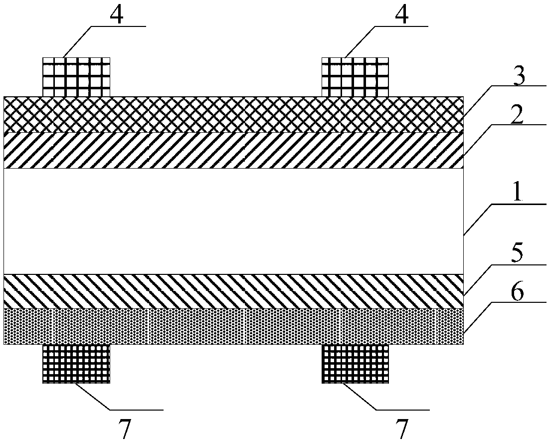
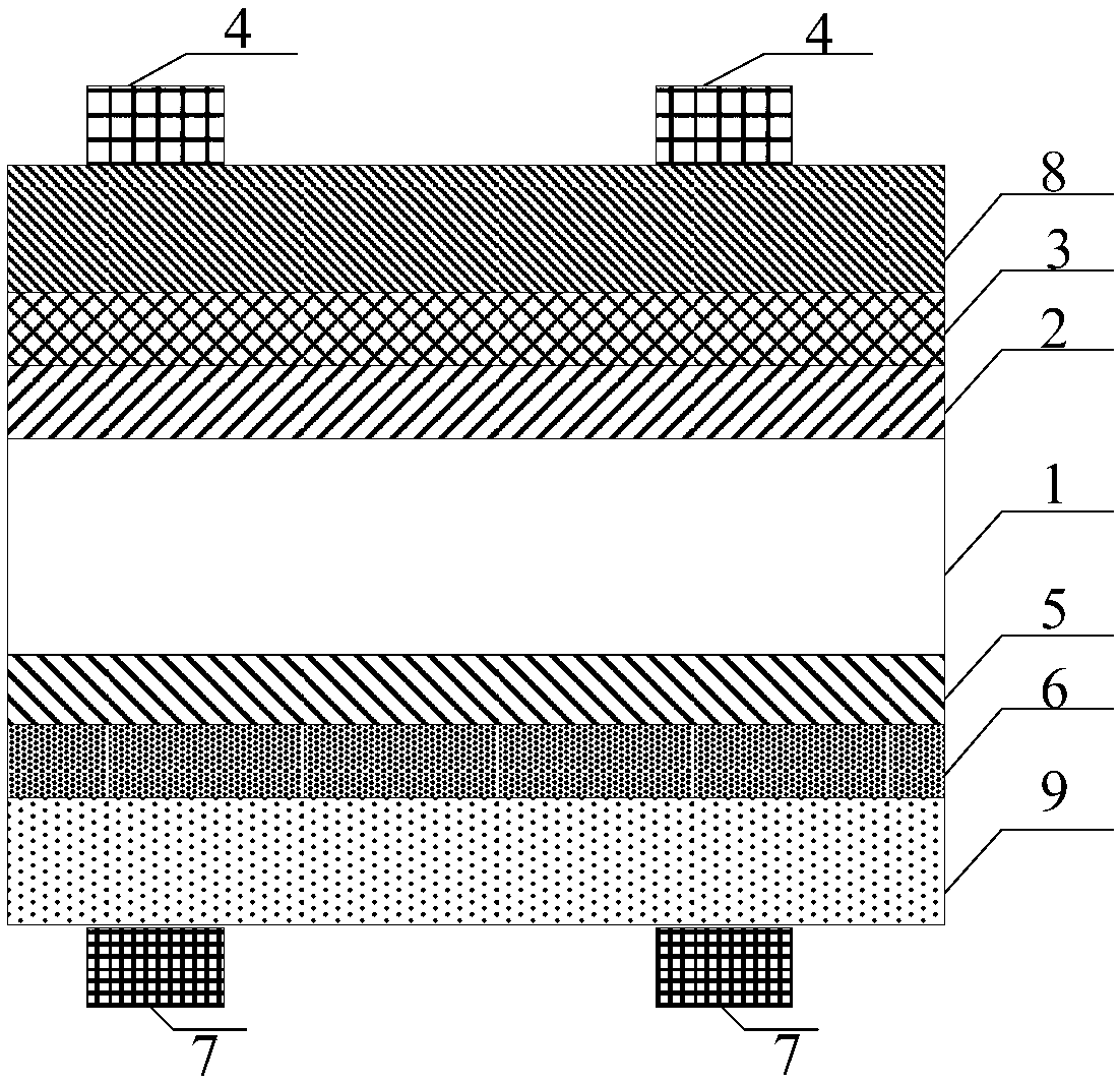
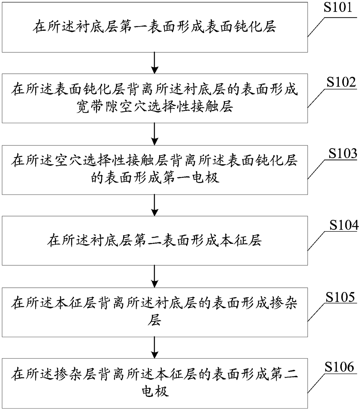
The present invention discloses a heterojunction solar cell. The heterojunction solar cell comprises: a substrate layer; a surface passivation layer located at the first surface of the substrate layer; a hole selectivity contact layer located at the surface, far away from the substrate layer, of the surface passivation layer, wherein the hole selectivity contact layer is a broad-band gap hole selectivity contact layer; a first electrode located at the surface, far away from the surface passivation layer, of the hole selectivity contact layer; an intrinsic layer located at the second surface ofthe substrate layer; a doping layer located at the surface, far away from the substrate layer, of the intrinsic layer; a second electrode located at the surface, far away from the intrinsic layer, ofthe doping layer, wherein the first surface is opposite to the second surface. The hole selectivity contact layer in the heterojunction solar cell is the broad-band gap hole selectivity contact layer, the band gap of the hole selectivity contact layer is broad and the light absorption range of the hole selectivity contact layer is small to greatly reduce the parasitic light absorption and improvethe solar cell short-circuit current density and photoelectric conversion efficiency. Besides, the present invention further provides a heterojunction solar cell preparation method having the advantages mentioned above.

Description

technical field [0001] The present application relates to the technical field of solar cells, in particular to a heterojunction solar cell and a preparation method thereof. Background technique [0002] Solar energy is a kind of renewable energy with unlimited reserves, free use, and green environmental protection. Solar cells can convert solar energy into electrical energy and provide clean energy for the society. Therefore, it has received extensive attention from countries all over the world. Among them, heterojunction solar cells use amorphous silicon thin films to realize the surface passivation and selective contact functions of crystalline silicon. They have the advantages of high photoelectric conversion efficiency, low temperature coefficient, no potential-induced attenuation and light-induced attenuation, and have great application potential. [0003] In traditional heterojunction solar cells, the band gaps of P-type amorphous silicon and intrinsic amorphous silico...

Claims


Application Information

Patent Timeline
IPC IPC(8): H01L31/0747H01L31/20H01L31/0288
CPCH01L31/0288H01L31/0747H01L31/202Y02E10/50Y02P70/50
Inventor 张树德魏青竹倪志春钱洪强连维飞揭建胜张晓宏
Owner SUZHOU TALESUN SOLAR TECH CO LTD
Learn More