
Preparation and application of humidity visual material with aggregation-induced emission characteristic

A technology of aggregation-induced luminescence and humidity, which is applied to luminescent materials, material analysis through optical means, and analysis of materials, etc. It can solve problems such as unsuitable for naked eye observation, unsuitable for accurate measurement, and non-luminous.

Active Publication Date: 2019-01-29
THE HONG KONG UNIV OF SCI & TECH
View PDF4 Cites 6 Cited by
  • Summary
  • Abstract
  • Description
  • Claims
  • Application Information

AI Technical Summary

Problems solved by technology

Several humidity sensing materials have been developed using the current fluorescent system, but there are the following problems: (i) The change of optical information is only expressed as the change of fluorescence intensity, which has a large dependence on the excitation power of the instrument and the sensitivity of the detector , not suitable for accurate measurement (Adv.Mater.2011,23,3770); (ii) the change of maximum excitation intensity in response to humidity changes is limited, not suitable for direct visual observation in a wide RH range (Ind.Eng.Chem .Res.2016,55,125); (iii) The sensor responds slowly, even taking tens of minutes, which is not suitable for in-situ real-time monitoring (J.Mater.Chem.2007,17,2989)
However, many traditional fluorescent molecules exhibit aggregation quenching phenomenon, showing weak light emission behavior or even no light emission in the condensed state.

Method used


Image

  • Preparation and application of humidity visual material with aggregation-induced emission characteristic
  • Preparation and application of humidity visual material with aggregation-induced emission characteristic
  • Preparation and application of humidity visual material with aggregation-induced emission characteristic

Examples


Embodiment 1

[0027] The TPE-Py or TPE-VPy fluorescent molecules are first dissolved in DMSO solvent to form a 1 mg / mL mother liquor. The molecular structure of TPE-py and TPE-Vpy is shown below;

[0028]

[0029] Take the above-mentioned 16uL TPE-Py or TPE-VP solution and mix with 150mg PAA polymer, and continue to stir for 2h, where PAA is dissolved in 3mL aqueous solution to obtain TPP and TVP solutions respectively;

[0030] Preparation of TPP and TVP films: spin-coated the above solution on the surface of quartz glass to obtain a humidity sensing film;

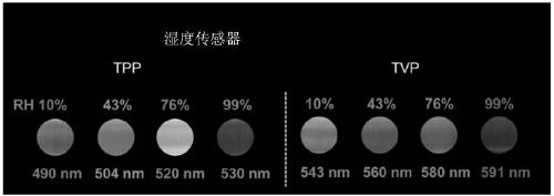
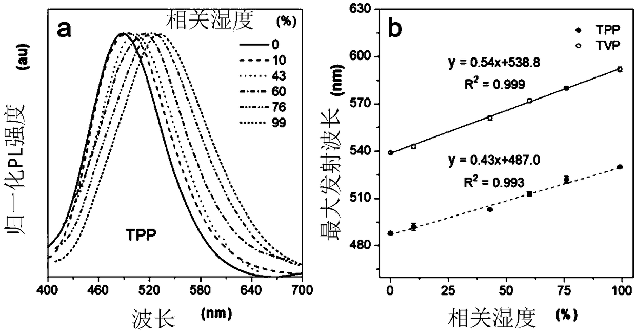
[0031] The obtained film was verified, the film was placed in a self-made humidity control box, and the above two materials were observed with the naked eye. It was found that under the excitation of the ultraviolet spectrum, the luminescence color of TPP and TVP materials under different humidity conditions occurred. Obvious redshift, such as figure 1 Shown. Furthermore, fluorescence spectroscopy is used to characterize the above films unde...

Embodiment 2

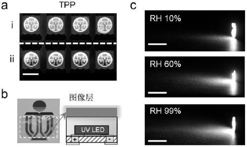
[0033] The AIE sensor with moisture-sensitive fluorescence luminescence characteristics provides a visual way to quantify the RH in a sealed package. by image 3 The package performance of the LED chip shown in a is proved. The surface of the LED chip is coated with TPP, and then the upper layer is encapsulated with silicone resin (PDMS). The organic silicon packaging system blocks the entry of water vapor in the surrounding area, and the fluorescent color of TPP has not changed. However, for the unencapsulated LED chips, the TPP emits red shift. In addition, inspired by traffic lights, a smart humidity LED light based on AIE sensors was demonstrated. Prepare transparent and flexible TPP film by drip coating method, and then integrate it into UV LED, such as image 3 Shown in b. When the ambient humidity increases ( image 3 c), the fluorescent color will automatically change from blue to green, and then to orange, and dynamic color feedback of relative humidity in a relative...

Embodiment 3

[0035] The water vapor is confined in the capillary, and its diffusion process is monitored to verify the ability of the AIE sensor to achieve high-resolution humidity change measurement in space. The present invention uses TPP aqueous solution to fill the glass capillary: first, the glass capillary is heated at 100°C to ensure complete removal of water. During the evaporation of water, TPP forms a uniform film on the inner surface of the glass capillary ( Figure 4 a). Fluorescence microscope observation shows that the thickness of the TPP film is about 16 μm. And the film emits green fluorescence, corresponding to an environmental RH value of 60%. A small amount of water is added to one end of the prepared capillary by capillary action. When heated, water vapor is generated and gradually diffuses into the capillary to form a humidity gradient distribution ( Figure 4 b). Through the use of Matlab for processing, the accurate determination of the RH value corresponding to ea...


PUM

PropertyMeasurementUnit
thicknessaaaaaaaaaa
thicknessaaaaaaaaaa

Abstract

A humidity sensing material according to the invention is obtained through assembling an aggregation-induced emission (AIE) fluorescent module with steam sensitivity and a hydrophilic high-polymer, thereby realizing humidity visual detection. In fluorescent detection, external connection with micro-electronic equipment is not required, and fluorescent-induced micro-environment polarity change is realized through external steam, and different naked-eye visible colors are obtained through UV light excitation. The fluorescent module rotor with the aggregation-induced emission (AIE) is used as thefunctional unit. The module is a donor-acceptor fluorescent module with conjugate and is based on a twisted module inner charge transfer (TICT) light emitting mechanism. Transmission spectrum band change in different-polarity micro-environment is used for obtaining a visible intelligent material with a corresponding humidity. The AIE humidity sensing material has an obvious light emitting wavelength change in different humidity conditions. A highest transmission wavelength and the humidity are in a linear relationship. Furthermore real-time accurate, quantitative and visible humidity detection is realized.

Description

Technical field [0001] The invention belongs to the cross-field of material composite and fluorescence induction device technology, and specifically relates to the preparation and application of a humidity visualization material with aggregation-induced luminescence characteristics. Background technique [0002] Humidity sensing plays an important role in life control systems and industrial monitoring processes. At present, various sensors have been developed to meet different applications. For atmospheric humidity measurement, remote sensing technologies such as microwave, millimeter wave, and terahertz (THz) provide almost all-weather atmospheric observation data on a global scale. In daily life, semiconductor sensors are mainly used for relative humidity (RH) measurement, and have the advantages of short response time, strong readability, and compatibility with other electronic devices. If the sensors have the characteristics of different configuration compatibility and spat...

Claims


Application Information

Patent Timeline
Patent Type & Authority Applications(China)
IPC IPC(8): C08L33/02C08K5/3432C08J5/18C09K11/06G01N21/64
CPCC08J5/18C08J2333/02C08K5/3432C09K11/06C09K2211/1425G01N21/6402C08L33/02
Inventor 唐本忠成艳华
Owner THE HONG KONG UNIV OF SCI & TECH
Learn More