
Method and system for measuring temperature of circuit coolant

A coolant temperature, coolant technology, applied in the direction of reducing greenhouse gases, climate sustainability, reactors, etc., can solve the problems of insufficient insertion depth of thermal resistance thermometers, cylinder wall thickness, etc.

Active Publication Date: 2019-01-25
CHINA NUCLEAR POWER TECH RES INST CO LTD +2
View PDF5 Cites 0 Cited by
  • Summary
  • Abstract
  • Description
  • Claims
  • Application Information

AI Technical Summary

Problems solved by technology

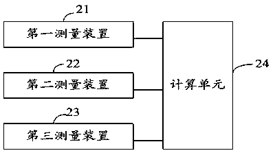
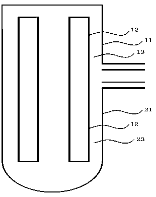
[0004] The technical problem to be solved by the present invention is to provide a method and system for measuring the temperature of the primary circuit coolant, by transferring the temperature measurement of the primary circuit coolant to the end of the once-through steam generator for measurement, and in the cylinder body of the steam generator The connecting nozzle is set on the flow channel of the steam generator spiral heat transfer tube assembly, and the temperature measuring instrument is inserted into the connecting nozzle, which solves the problem that the wall of the DC steam generator cylinder is too thick and the insertion depth of the thermal resistance thermometer is not enough

Method used


Image

  • Method and system for measuring temperature of circuit coolant
  • Method and system for measuring temperature of circuit coolant
  • Method and system for measuring temperature of circuit coolant

Examples


Embodiment Construction

[0039] The following descriptions of various embodiments refer to the accompanying drawings to illustrate specific embodiments in which the present invention can be implemented.

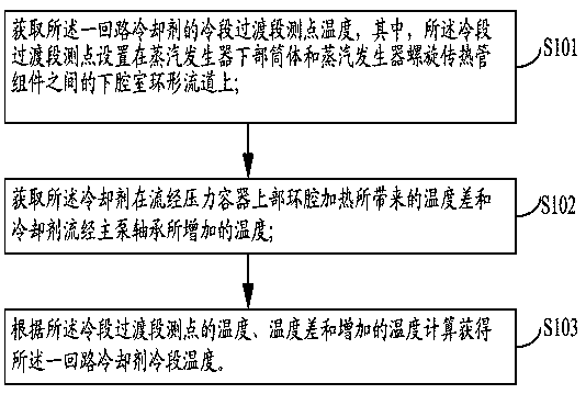
[0040] refer to figure 1 As shown, Embodiment 1 of the present invention provides a method for measuring the temperature of the cold section of a coolant in a primary circuit, including the following steps:

[0041] Step S101. Obtain the temperature of the measuring point in the transition section of the cold section of the primary circuit coolant, wherein the measuring point in the transition section of the cold section is set at the lower part between the lower cylinder of the steam generator and the spiral heat transfer tube assembly of the steam generator. On the annular flow channel of the chamber.

[0042] Step S102, obtaining the temperature difference caused by the coolant flowing through the upper annular cavity of the pressure vessel and the temperature increase caused by the coolant flow...


PUM


Abstract

The present invention provides a method and a system for measuring the temperature of a circuit coolant. The method comprises: obtaining the temperature of a circuit coolant at a cooling section transition section measuring point, wherein the cooling section transition section measuring point is arranged on a lower chamber annular flow channel between a steam generator lower cylinder and a steam generator spiral heat transfer tube assembly; obtaining the temperature difference and the increased temperature, wherein the temperature difference is generated when the coolant flows through the upper annular chamber of a pressure container to heat, and the increased temperature is generated when the coolant flows through a main pump bearing; and according to the temperature at the cooling section transition section measuring point, the temperature difference and the increased, calculating to obtain the cooling section temperature of the circuit coolant. According to the present invention, the temperature measuring connection pipe nozzle is arranged on the internal flow channel of the once-through steam generator, the fast response thermal resistance thermometer with the protection bushing is inserted into the connection pipe nozzle, and the temperature of the circuit coolant is measured, such that the problem that the measuring point cannot be arranged in the compact small-size reactor due to the absence of the main pipe section is solved, and the problem that the inserting depth cannot be met due to the wide flow channel and the short thermometer length is solved.

Description

technical field [0001] The invention relates to the technical field of nuclear power instrument control and equipment, in particular to a method and system for measuring primary circuit coolant and temperature. Background technique [0002] In a pressurized water reactor nuclear power plant, the temperature of the reactor coolant represents the temperature of the primary circuit of the reactor. It is used in the reactor protection system and is an important process measurement parameter. When the temperature of the coolant is too high or too low, it will directly trigger shutdown. Protect. [0003] The temperature measurement of the reactor coolant in the existing commercial large-scale pressurized water reactor nuclear power plant is all on the main loop section of the primary circuit (such as Figure 7 As shown), due to the compact design of the small reactor, short casings are used to connect the pressure vessel, the steam generator and the main pump, and there is no conn...

Claims


Application Information

Patent Timeline
IPC IPC(8): G21C17/022G21C17/017
CPCG21C17/017G21C17/022Y02E30/30
Inventor 何小明黄勇郭伟郑文强
Owner CHINA NUCLEAR POWER TECH RES INST CO LTD
Learn More