
Feeding mechanism for temperature limiter cup

A technology of feeding mechanism and warmer cup, applied in the direction of feeding device, metal processing equipment, manufacturing tools, etc., can solve the problems of low stamping efficiency, high labor intensity of workers, and cumbersome steps

Inactive Publication Date: 2019-01-25
信宜市翔胜家电科技有限公司
View PDF0 Cites 0 Cited by
  • Summary
  • Abstract
  • Description
  • Claims
  • Application Information

AI Technical Summary

Problems solved by technology

At present, because this process requires multiple action steps, the steps are cumbersome, and the method of manual feeding and punching is still used. Not only the stamping efficiency is low, but also accidents of stamping head injuries are easy to occur, and the labor intensity of workers is high.

Method used


Image

  • Feeding mechanism for temperature limiter cup
  • Feeding mechanism for temperature limiter cup
  • Feeding mechanism for temperature limiter cup

Examples


Embodiment Construction

[0011] Below with reference to the accompanying drawings, through the description of the implementation examples, the specific embodiments of the present invention, such as the shape, structure, mutual position and connection relationship between each part, the role and working principle of each part, etc., will be further described. detailed instructions.

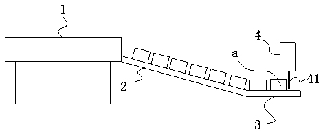
[0012] Such as image 3 , 4 , the temperature limiter cup feeding mechanism of the present invention includes a vibrating plate 1 for vibrating the temperature limiter cup body a into a state where the cup opening a0 faces downward, and the discharge port of the vibrating plate 1 is connected with an inclined downward setting Conveyor belt 2, the bottom of the conveyor belt 2 is connected with a straight section material belt 3, the top of the straight section material belt 3 is provided with a retaining cylinder 4, and the retaining cylinder 4 is provided with a direction to the straight section material belt 3 The over...


PUM


Abstract

The invention provides a feeding mechanism for a temperature limiter cup. The temperature limiter cup can be automatically overturned and arrayed one by one, which helps to achieve full-automatic punching of the temperature limiter cup, improve the punching efficiency and avoid hand injury accidents. The mechanism comprises a vibration disc used for vibrating the temperature limiter cup to be in astate with a downward cup opening, a discharging port of the vibration disc is connected with a conveying belt which is obliquely and downwards arranged, and a straight-segment material band is connected to the bottom of the conveying belt; a blocking air cylinder is arranged above the straight-segment material band and provided with a blocking retractable rod which is suspended towards the end face of the straight-segment material band.

Description

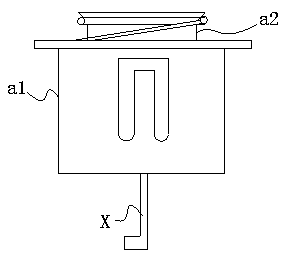
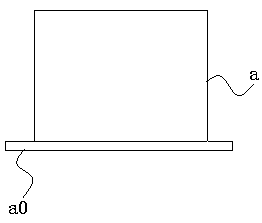
technical field [0001] The invention relates to the technical field of home appliance spare parts processing equipment, in particular to a temperature limiter cup feeding mechanism. Background technique [0002] Magnetic steel temperature limiter structure attached for rice cooker temperature sensing figure 1 As shown, it includes a temperature limiter outer cup a1 and a temperature limiter inner cup a2, and the bottoms of the temperature limiter outer cup a1 and the temperature limiter inner cup a2 need to be punched out for the hook X to pass through. The primary forming of the temperature limiter cup body a is to continuously punch out a blank in the shape of the cup body on the thin steel plate, and then perform the next step of punching through holes. Since the blank is already in the shape of a cup body, when punching the through hole, it needs to be inverted so that the cup mouth a0 faces down, and then the cup mouth a0 is aligned and inserted into the stamping die f...

Claims


Application Information

Patent Timeline
IPC IPC(8): B21D43/16B21D43/10
CPCB21D43/16B21D43/105
Inventor 黄正凌
Owner 信宜市翔胜家电科技有限公司
Learn More