Laser cladding method and device for metal round rod surface

A technology of laser cladding and round rods, which is applied in the coating process of metal materials, coating, etc., can solve the problems that cannot really meet the requirements of the cladding parts, poor performance of joint parts, waste of precious powder, etc., and achieve simple structure , cladding time is short, the effect of reducing the generation of pores

Active Publication Date: 2020-11-24
HUNAN UNIV OF TECH
View PDF7 Cites 0 Cited by
  • Summary
  • Abstract
  • Description
  • Claims
  • Application Information

AI Technical Summary

Problems solved by technology

[0003] In the traditional laser cladding process, a low-power laser is usually used for cladding, and its power is generally 3,000 to 5,000 watts. During the cladding process, the laser cladding nozzle moves along the axial direction of the cladding (cylindrical) , while the cladding part only rotates, but the laser cladding nozzle may vibrate greatly during the moving process, resulting in unhealthy problems such as uneven powder feeding. When the vibration frequency is high, it is necessary to install a shock absorber. In addition, laser cladding The amount of powder sprayed out by the nozzle is small, and the line of the laser cladding nozzle on the surface of the cladding part is as thin as a "ballpoint pen line". As a result, each cladding range is small, the time is long, and the cladding efficiency is low. Moreover, the performance of the cladding connection part is poor, which cannot really meet the requirements of the cladding parts.
[0004] In addition, the laser cladding process in the prior art is mainly aimed at cylindrical parts with large diameters. For the time being, there is no cladding method and device specifically for cladding metal round rods with slender features. When cladding a cylindrical part, the cladding powder stays on the surface of the cylindrical part for a long time and is easy to be clad, while the metal round rod is limited by its small diameter shape characteristics, such as copying the laser cladding process for cylindrical parts , the contact time between the cladding powder and the surface of the metal round rod will be very short, and it is difficult to be completely clad on the surface of the metal round rod in a short time, so the surface of the metal round rod obtained by cladding will have a large area in an unclad state , and in the process of laser cladding metal round rods, it often causes a lot of waste of precious powder

Method used


Image

  • Laser cladding method and device for metal round rod surface
  • Laser cladding method and device for metal round rod surface
  • Laser cladding method and device for metal round rod surface

Examples


Embodiment 1

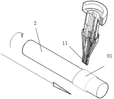
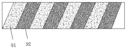
[0028] A method for laser cladding on the surface of a metal round rod, specifically: prepare a laser, the laser cladding nozzle of the laser is located on the outer peripheral surface near the end of the metal round rod, the position of the laser cladding nozzle is fixed, and the metal The round bar can not only rotate at a constant speed but also move at a constant speed along the axial direction at the same time, so that the movement track of the laser cladding nozzle relative to the metal round bar is a helical line along the surface of the metal round bar, that is, it moves forward while rotating with the metal round bar. , from a perspective, the surface of the metal rod will form a number of cladding rings that are closely connected and have a certain angle.

[0029] In order to further improve the cladding efficiency, the nozzle of the laser cladding nozzle in this method has a flat rectangular opening structure, and the long side of the rectangular opening structure is...

Embodiment 2

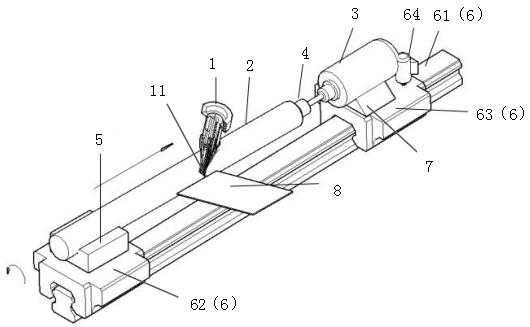
[0032] Such as figure 1 As shown, a metal round rod surface laser cladding device is provided, which includes a laser (only the laser cladding nozzle 1 is shown) and a rotating motor 3 that can drive the metal round rod 2 to rotate at a uniform speed. The first ends of the rods 2 are connected by a connecting device 4, and a support platform 5 adapted to the outer peripheral surface of the metal round rods is provided under the second ends of the metal round rods 2 to support the metal round rods 2 in a horizontal arrangement; the laser of the laser The cladding nozzle 1 is located near the outer peripheral surface of either end of the metal round rod 2; it also includes a linear sliding mechanism 6 arranged below the metal round rod 2 and parallel to the axis of the metal round rod, and the support table 5 and the rotating motor 3 are both provided On the linear sliding mechanism 6, the linear sliding mechanism 6 can drive the metal round rod 2 to move at a constant speed in ...

Embodiment 3

[0048] The difference between this embodiment and Embodiment 2 is that the high temperature resistant baffle is set horizontally, which can also collect excess powder and realize immediate reuse.


PUM


Abstract

The invention belongs to the field of laser cladding, and discloses a method and device for laser cladding of the surface of a metal round rod. A laser is prepared; a laser cladding nozzle of the laser is located near the peripheral surface of the end of the metal round rod, so that the metal round rod can move at a uniform speed in the axial direction while rotating at a uniform speed, and the movement trajectory of the laser cladding nozzle relative to the metal round rod is a spiral line along the surface of the metal round rod. The method of laser cladding on the surface of the metal roundrod subverts a traditional idea of cladding by moving the laser cladding nozzle, but a way that the laser cladding nozzle is stationary while the metal round rod moves in a straight line and in a whirling way simultaneously is adopted. Therefore, the final cladding layer on the surface of the metal round rod is a spiral line and the performance of the cladding connection part is stable.

Description

technical field [0001] The invention relates to the technical field of laser cladding, in particular to a method and device for laser cladding on the surface of a metal round bar. Background technique [0002] Laser cladding refers to placing the selected coating material on the surface of the cladding substrate in different ways of adding materials, irradiating it with laser to melt it and a thin layer on the surface of the substrate at the same time, and forming a very low dilution after rapid solidification. The surface coating that is metallurgically combined with the substrate is a process method that significantly improves the wear resistance, corrosion resistance, heat resistance, oxidation resistance and electrical properties of the base surface, so as to achieve the purpose of surface modification or repair, and can meet the specific needs of the material surface. Performance requirements, but also save a lot of precious elements. [0003] In the traditional laser ...

Claims


Application Information

Patent Timeline
Patent Type & Authority Patents(China)
IPC IPC(8): C23C24/10
CPCC23C24/10
Inventor 阳建君范才河孙斌欧玲黎伟华吴艳辉李芳芳丁燕鸿蹇海根
Owner HUNAN UNIV OF TECH
Why Eureka
Try Eureka