
A system and application method for efficient and uniform processing of various profiles by ultrasonic shot peening

An ultrasonic shot peening and shot peening technology, used in metal processing equipment, manufacturing tools, abrasive jetting machine tools, etc., can solve the problem of difficult to process concave surfaces, low processing speed, shot peening speed, and precision control of processing areas. The uniformity of processing is difficult to control. and other problems to achieve the effect of avoiding acute angles and uniform surface treatment

Active Publication Date: 2020-09-01
CENT SOUTH UNIV
View PDF11 Cites 2 Cited by
  • Summary
  • Abstract
  • Description
  • Claims
  • Application Information

AI Technical Summary

Problems solved by technology

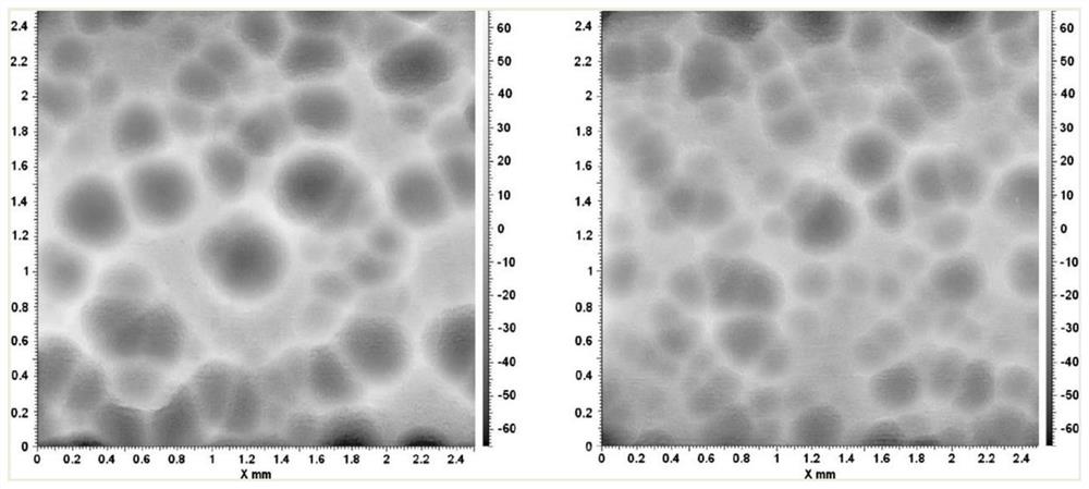
However, due to the limitation of the principle of ultrasonic shot peening, it is difficult to control the speed of shot peening, the precise control of the processing area and the uniformity of processing. The formation of ultrasonic shot peening is usually as follows: figure 1 For the surface shown, it is difficult to process a large concave surface on the surface of the workpiece. The relatively large concave surface is more helpful to improve the fatigue resistance of the workpiece surface. The medium with a relatively large diameter has a low processing speed, and it is difficult to process a large concave surface. , which is not conducive to shot blasting, and the surface treatment is not uniform enough, and there will be acute angles at the connection between the concave surface and the convex surface

Method used

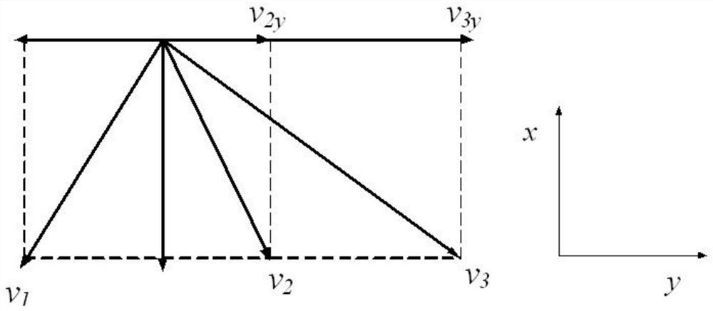

Image

  • A system and application method for efficient and uniform processing of various profiles by ultrasonic shot peening
  • A system and application method for efficient and uniform processing of various profiles by ultrasonic shot peening
  • A system and application method for efficient and uniform processing of various profiles by ultrasonic shot peening

Examples


Embodiment Construction

[0028] The present invention will be described in detail below in conjunction with the accompanying drawings and embodiments.

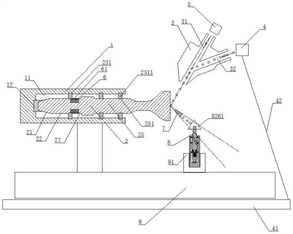
[0029] refer to image 3 , a system for ultrasonic shot peening of the present invention to efficiently and uniformly process various profiles, including a workpiece clamping mechanism 8, a workbench 9, and a first connecting piece 1 and a first vibration horn 2 arranged on the workbench 9 , mixer 3, shot blasting filling device 4, air injection mechanism 5, drive mechanism 91, control system; one end of the first vibration horn 2 is embedded in the first connector 1, and the other end is provided with an end face for rebound shot peening , the first vibration horn 2 is equipped with a pair of first piezoelectric actuators 6 opposite to each other. The direction is arranged at intervals, the first piezoelectric actuator 6 is connected with the ultrasonic generator; the gas injection mechanism 5 is used to rush the compressed gas into the mixer 3; the...


PUM


Abstract

The invention discloses an ultrasonic shot blasting efficient and uniform processing system for various molded surfaces. The system comprises a workpiece clamping mechanism, a working table and a first connecting member arranged on the working table, a first vibration amplitude transformer, a mixer, a shot blast filling device, a jet mechanism, a driving mechanism, and a control system; a pair ofoppositely positioned first piezoelectric actuators are arranged at the first vibration amplitude transformer; the mixer is located above the first vibration amplitude transformer, and is used for mixing the compressed gas and the shot blast, the shot blast is sprayed to the end surface of the first vibration amplitude transformer, and the shot blast is accelerated by end surface rebounding to process a workpiece at a lower part; The workpiece clamping mechanism includes a second connecting member, a second vibration amplitude transformer, the second vibration amplitude transformer is mountedwith a second piezoelectric actuator, and is capable of generating axial-bending-torsional coupling vibration. The system can improve the speed of shot blast processing, under the action of the vibration of the second vibration amplitude transformer, the workpiece is uniformly processed at a high speed, and efficient processing of the workpiece is realized.

Description

technical field [0001] The invention relates to the field of shot peening, in particular to a system and a method for efficiently and uniformly processing various profiles by ultrasonic shot peening. Background technique [0002] At present, the ultrasonic shot peening method is widely used in various surface treatment processes of workpieces, which can significantly reduce the residual stress on the surface of the workpiece, improve the fatigue strength of the workpiece, and help form a convex-concave joint surface for high-strength connections or lubricated connections . However, due to the limitation of the principle of ultrasonic shot peening, it is difficult to control the speed of shot peening, the precise control of the processing area and the uniformity of processing. The formation of ultrasonic shot peening is usually as follows: figure 1 For the surface shown, it is difficult to process a large concave surface on the surface of the workpiece. The relatively large ...

Claims


Application Information

Patent Timeline
Patent Type & Authority Patents(China)
IPC IPC(8): B24C1/10B24C3/04B24C7/00B24C9/00
CPCB24C1/10B24C3/04B24C7/0046B24C9/00B24C9/006
Inventor 唐进元赵久越陈雪林
Owner CENT SOUTH UNIV
Learn More