Steel bar crushing method and steel bar crushing equipment adopting same

A technology of crushing equipment and crushing methods, applied in the direction of grain processing, etc., can solve the problems of unfavorable steel scrap utilization, long length, low efficiency, etc., and achieve the effects of good adaptability, improved efficiency and quality, and improved reliability

Inactive Publication Date: 2019-01-15
JIANGYIN GUANGFU MACHINERY
View PDF5 Cites 0 Cited by
  • Summary
  • Abstract
  • Description
  • Claims
  • Application Information

AI Technical Summary

Problems solved by technology

[0004] In the prior art, the fragmentation of steel bars is usually done manually by using a hand-held grinder to cut off the steel bars one by one. On the one hand, the efficiency is extremely low. On the other hand, the length of the steel bars after cutting is long, which is not conducive to the subsequent treatment of waste. Utilization of steel bars

Method used


Image

  • Steel bar crushing method and steel bar crushing equipment adopting same
  • Steel bar crushing method and steel bar crushing equipment adopting same
  • Steel bar crushing method and steel bar crushing equipment adopting same

Examples


Embodiment 1

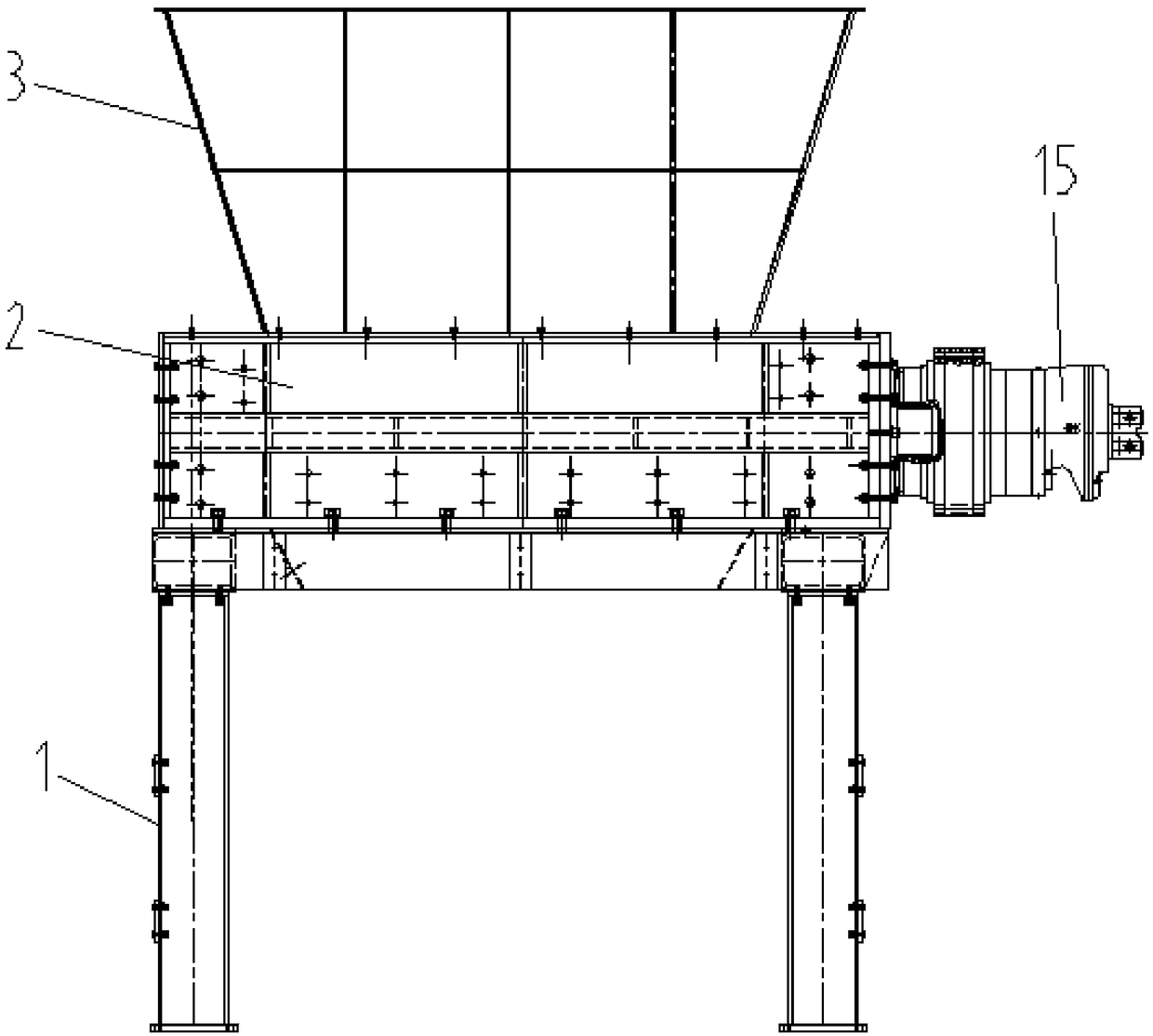
[0060] Such as Figures 1 to 5 Shown is the embodiment of a kind of steel bar crushing method of the present invention, comprises following method:

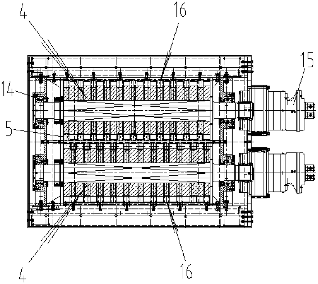
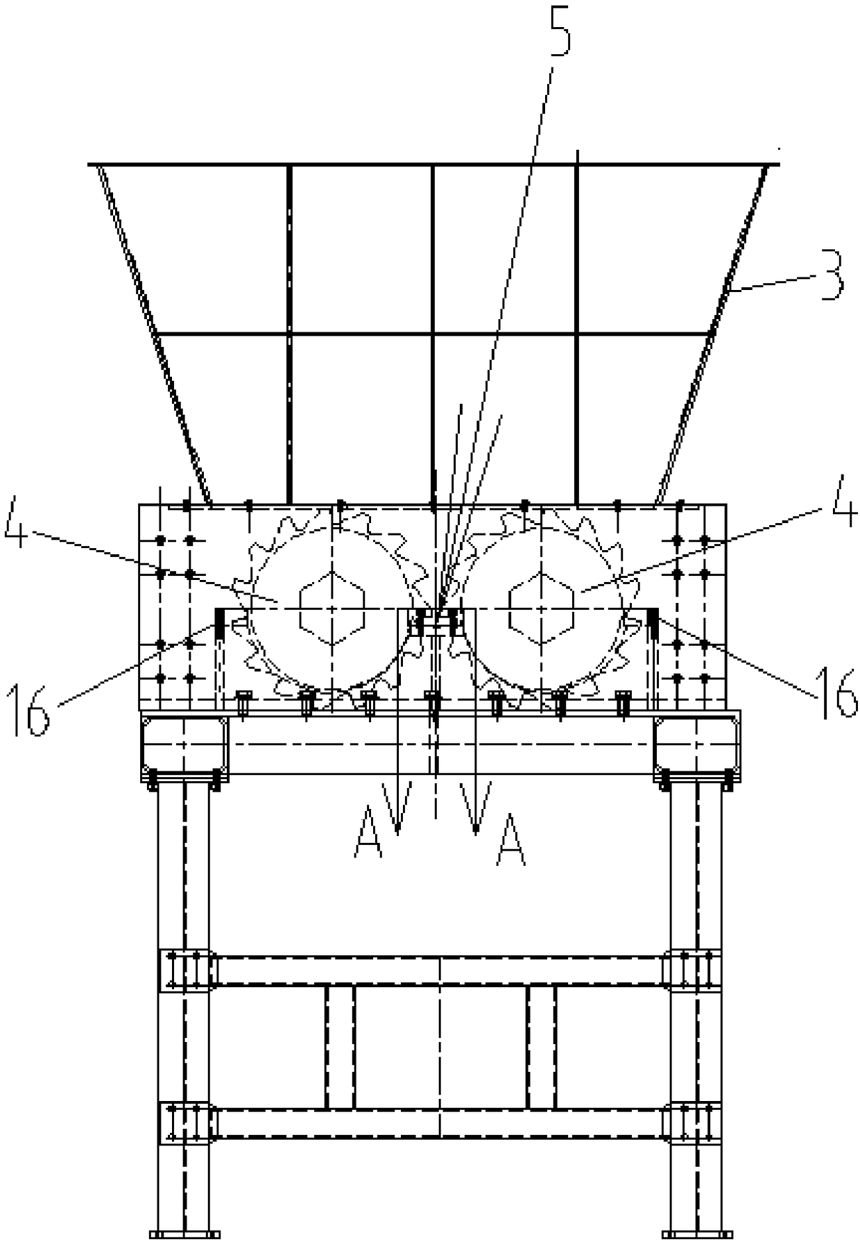
[0061] (1), a pair of rotating knife shafts 4 and a main shearing knife seat 5 are arranged, and a pair of rotating knife shafts 4 are placed on both sides of the main shearing knife seat 5;

[0062] (2), cutterhead 7 is set on rotary cutter shaft 4, shearing knife tooth 8 is set on cutterhead 7, groove 9 that runs through up and down for shearing is set on main shearing knife seat 8, shearing knife The tooth width sides and tooth tops of the tooth 8 are respectively matched with the sides of the groove 9 for shearing and the bottom of the groove 9;

[0063] (3), drop steel bar downwards from the upper part of the main shearing knife holder 5, so that the steel bar falls between a pair of rotating knife shafts 4;

[0064] (4), the rotary cutter shaft 4 rotates, and the shearing knife teeth 8 on the rotary cutter shaft 4 hook th...

Embodiment 2

[0071] Such as Figures 1 to 5 Shown is an embodiment of a steel bar crushing equipment of the present invention, including a crushing chamber 2, a feeding hopper 3 connected above the crushing chamber 2, and a rotatable device for shearing and crushing steel bars is arranged in the crushing chamber 2. A pair of rotary cutter shafts 4, a main shearing knife seat 5 compatible with the pair of rotary cutter shafts 4 is fixedly arranged between the pair of rotary cutter shafts 4, and the rotary cutter shafts 4 include a rotating shaft 6 and a certain number of cutterheads 7 arranged on the rotating shaft 6 and distributed at intervals, the cutterhead 7 is provided with a number of shearing teeth 8 along the circumferential direction, and the main shearing knife seat 5 is provided with The tooth width sides of the shearing knife teeth 8 are matched with grooves 9 at the tops of the teeth, and the grooves 9 are vertically connected.

[0072] During work, the scrap steel bars are c...


PUM


Abstract

The invention relates to the technical field of material crushing and discloses a steel bar crushing method and steel bar crushing equipment adopting the crushing method. The steel bar crushing equipment comprises a pair of rotating cutter shafts and a main shearing cutter seat, wherein the pair of the rotating cutter shafts are correspondingly arranged on two sides of the main shearing cutter seat. Cutter heads are arranged on the rotating cutter shafts, shearing cutter teeth are arranged on the cutter heads, a shearing groove penetrating up and down is formed in the main shearing cutter seat, and the two sides of the tooth width and the tooth top of each shearing cutter tooth are correspondingly matched with the two sides and the groove bottom of the shearing groove. A steel bar is thrown downward from the upper part of the main shearing cutter seat, so that the steel bar falls between the pair of rotating cutter shafts. The rotating cutter shafts rotate, the shearing cutter teeth onthe rotating cutter shafts hook the steel bar, and the steel bar is pressed down to the upper plane of the main shearing cutter seat. The rotating cutter shafts continue to rotate to press and shearthe steel bar located at the groove in the main shearing cutter seat. The steel bar crushing method and the steel bar crushing equipment realize the automation of steel bar crushing and further improve the efficiency and quality of steel bar crushing.

Description

technical field [0001] The invention relates to the technical field of material crushing, in particular to a steel bar crushing method and steel bar crushing equipment adopting the crushing method. Background technique [0002] Rebar is a type of steel used in reinforced concrete buildings or building elements, usually circular in cross-section, sometimes square with rounded corners, including plain round bars, ribbed bars, twisted bars, etc. [0003] During the demolition process of urban buildings, a large number of scrap steel bars will be produced. These scrap steel bars have different shapes and are often entangled. In order to realize the recycling of the scrap steel bars, the scrap steel bars need to be shredded during the processing of the scrap steel bars, that is, the steel bars are cut into small sections or granular shapes for subsequent further processing. [0004] In the prior art, the fragmentation of steel bars is usually done manually by using a hand-held g...

Claims


Application Information

Patent Timeline
Patent Type & Authority Applications(China)
IPC IPC(8): B02C18/14B02C25/00B02C18/16
CPCB02C18/14B02C18/16B02C25/00
Inventor 钱红陈惠清钱烈
Owner JIANGYIN GUANGFU MACHINERY
Why Eureka
Try Eureka