An energy storage type vehicle and an automatic charging detection system thereof

An automatic charging and detection system technology, applied in electric vehicle charging technology, vehicle components, vehicle energy storage, etc., can solve problems such as short charging area, vehicle arcing, and arcing in and out of stations, so as to reduce the risk of failure and reduce the Difficulty, the effect of reducing arcing phenomenon

Active Publication Date: 2018-12-21
ZHUZHOU ELECTRIC LOCOMOTIVE CO LTD
View PDF3 Cites 2 Cited by
  • Summary
  • Abstract
  • Description
  • Claims
  • Application Information

AI Technical Summary

Problems solved by technology

During the charging and power-off process mentioned above, the charging and power-off of the vehicle can be fully realized due to the need to rely on the cooperation of the in-station detection device and the out-station detection device. Once one of the two fails, the vehicle charging failure
For example, the detection device for entering the station is in normal operation. When the vehicle enters the station, the charging device controls the conductive rail to charge the vehicle. During or before the charging process, the detection device for exiting the station fails. When the vehicle exits the station, the charging device does not receive When the exit signal is reached, the vehicle will continue to be charged, causing arcing phenomenon after the vehicle exits the station, and even damage to the energy storage unit of the vehicle, carbonization of the conductive rail surface, etc.
And because the inbound detection device and the outbound detection device need to be installed at the two ends of the inbound and outbound respectively, once the setting position is unreasonable, it is likely to cause the inbound signal and the outbound signal to occur at the same time during the signal transmission process. Overlapping, or the charging area is too short, arcing occurs both when entering and leaving the station, etc.

Method used


Image

  • An energy storage type vehicle and an automatic charging detection system thereof

Examples


Embodiment Construction

[0021] The following will clearly and completely describe the technical solutions in the embodiments of the present invention in conjunction with the accompanying drawings in the embodiments of the present invention. Obviously, the described embodiments are only some of the embodiments of the present invention, not all of them. Based on the embodiments of the present invention, all other embodiments obtained by persons of ordinary skill in the art without making creative efforts belong to the protection scope of the present invention.

[0022] The core of the present invention is to provide an energy storage vehicle and its automatic charging detection system, which are used to improve the reliability of the charging process and avoid arcing.

[0023] In order to enable those skilled in the art to better understand the solution of the present invention, the present invention will be further described in detail below in conjunction with the accompanying drawings and specific emb...


PUM


Abstract

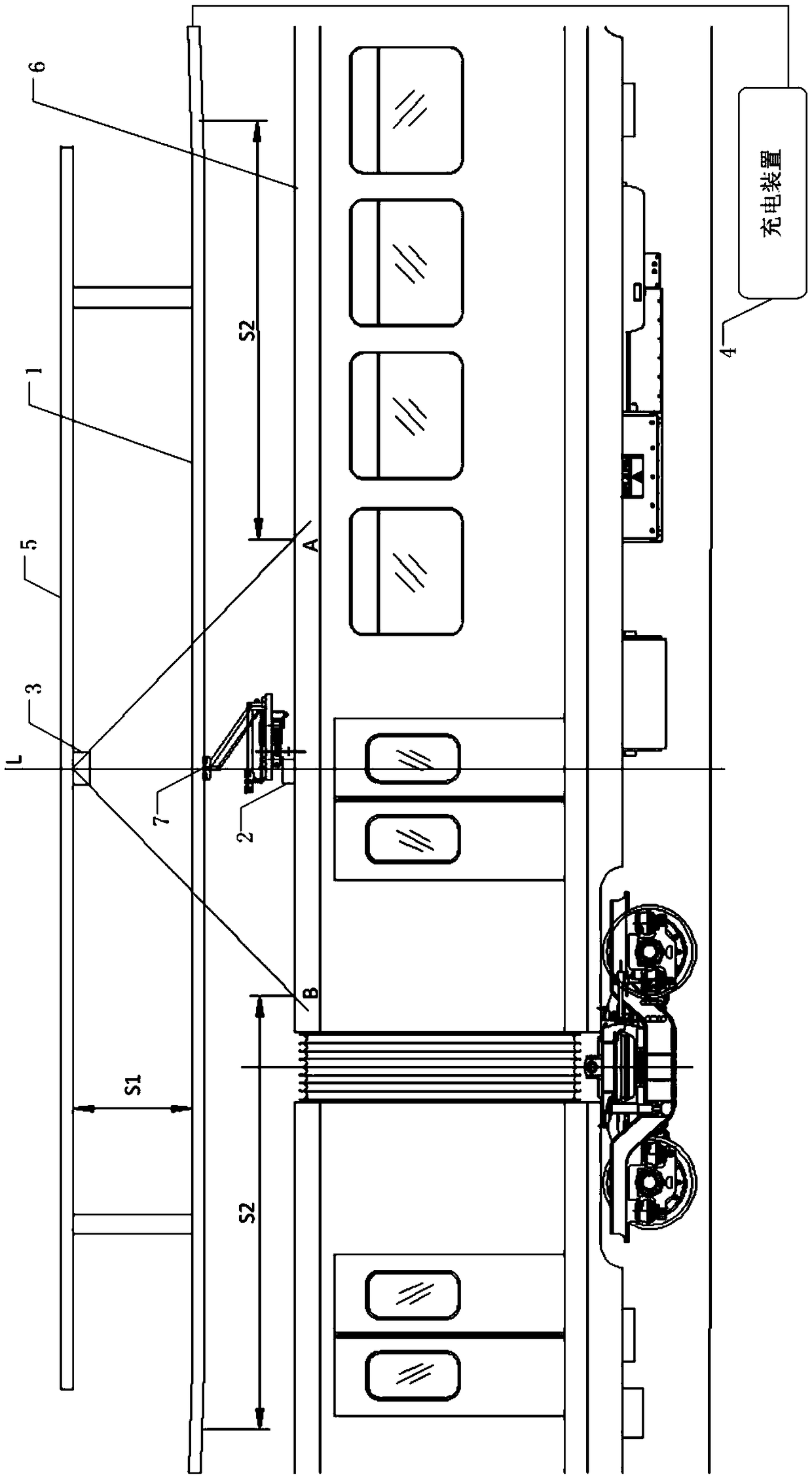
The invention discloses an energy storage type vehicle and an automatic charging detection system thereof, which comprises a conductive rail, a signal transmitter, a signal receiver and a charging device. Wherein one of a signal receiver and a signal transmitter is disposed within the station, ehe other one is mounted on the roof of the vehicle. Because the signal receiver and the signal transmitter can transmit the signal effectively within a certain range, the signal transmission state between the two devices is different with the moving of the vehicle, so that the signal entering and leaving the station of the vehicle can be detected. In accordance with that prior art, As that detection device are respectively arranged at the inbound end and the outbound end, In this system, a set of devices can be used to complete the detection, which reduces the risk of failure of a certain detection device, and then reduces the occurrence of arc phenomenon. In addition, the signals of incoming and outgoing stations are generated by this set of devices, and no matter where they are located; no signal overlap will be generated. Therefore, the difficulty of installation position is reduced.

Description

technical field [0001] The invention relates to the field of energy storage vehicles, in particular to an energy storage vehicle and an automatic charging detection system thereof. Background technique [0002] The energy storage vehicles mentioned in this application are mainly energy storage rail vehicles. The charging method of the energy storage rail vehicles is hard-wired connection charging. In order to ensure the safety of the vehicles, under normal circumstances, the vehicles start charging after entering the station. Power off after leaving the station. [0003] In the prior art, an in-station detection device and an out-station vehicle inspection device are respectively installed at the two ends of the vehicle entry and exit. The device controls the conductive rail to charge the vehicle. When the vehicle exits the station, the exit detection device detects that the vehicle exits the station and sends an exit signal to the charging device. The charging device contr...

Claims


Application Information

Patent Timeline
Patent Type & Authority Applications(China)
IPC IPC(8): B60L11/18B60L5/38
CPCB60L5/38B60L2200/26Y02T10/70Y02T10/7072Y02T90/12
Inventor 龙源柯建明张伟先胡润文文午唐艳丽张婷婷付亚娥付鹏李玉梅陈朝晖陈盛才
Owner ZHUZHOU ELECTRIC LOCOMOTIVE CO LTD
Why Eureka
Try Eureka