A 3D-MID technology array antenna

A 3D-MID and array antenna technology, applied in the field of 3D-MID technology array antenna, can solve problems affecting the performance of the antenna system, and achieve the effects of improving directivity and gain, improving isolation, and increasing bandwidth

Pending Publication Date: 2018-12-11
TONGYU COMM INC
View PDF8 Cites 9 Cited by
  • Summary
  • Abstract
  • Description
  • Claims
  • Application Information

AI Technical Summary

Problems solved by technology

[0004] The purpose of the present invention is to provide a 3D-MID technology array antenna to solve the problem that the existence of mutual coupling phenomenon in the existing MIMO antenna system seriously affects the performance of the antenna system. Inter-loading magnetic negative metamaterial elements to achieve decoupling

Method used


Image

  • A 3D-MID technology array antenna
  • A 3D-MID technology array antenna
  • A 3D-MID technology array antenna

Examples


Embodiment Construction

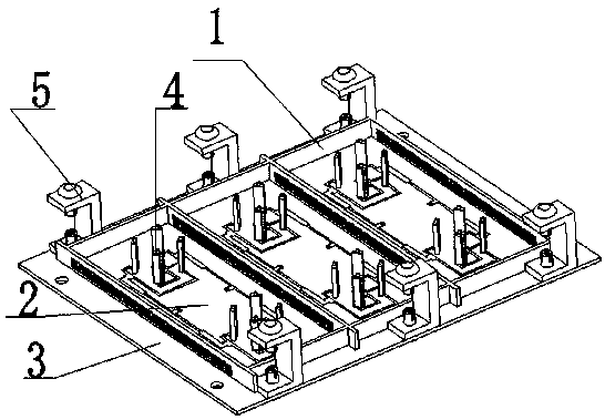
[0027] As shown in the figure, the specific implementation method is as follows:

[0028] A 3D-MID technology array antenna, including a feeder line dielectric substrate 3, one side of the feeder line dielectric substrate 3 is provided with a metal ground 301, the metal ground 301 can replace the metal reflector in the traditional antenna array, reducing The number of components of the antenna array is reduced, and the volume and weight of the antenna array are greatly reduced, and at the same time, the electrical performance is guaranteed to be reliable. Zone 2, the antenna unit is arranged in the isolation zone 2, and the isolation strips of two adjacent two antenna units are composed of a magnetic negative metamaterial unit 6, and the magnetic negative metamaterial unit 6 is composed of two square spiral resonators 601 cascaded, and the two The magnetic negative metamaterial unit 6 composed of four square spiral resonators 601 cascaded is placed between two adjacent antenna...


PUM


Abstract

A 3D-MID technology array antenna includes a feed line dielectric substrate, A surface of one side of that dielectric substrate of the feed line is provided with a metal ground, At that other side ofthe dielectric substrate of the feed line, a plurality of isolation regions distribute in an array are formed around the dielectric substrate by the isolation strips, An antenna unit is arranged in the isolation area, the isolation strips of two adjacent antenna elements are composed of magneto-negative metamaterial elements, A magnetonegative metamaterial element consist of two square helical resonators in cascaded connection, A magnetic negative metamaterial unit consisting of two square helical resonators in cascaded connection is placed between two adjacent antenna units to act as an isolation strip, and the isolation degree is improved at the same time of decoupling. The invention achieves the purpose of decoupling by loading a magnetic negative metamaterial unit between the antenna units from the perspective of restraining mutual coupling.

Description

technical field [0001] The invention relates to the technical field of mobile communication base stations, in particular to a 3D-MID technology array antenna. Background technique [0002] With the improvement of the integration of electronic equipment, the volume of communication equipment is getting smaller and smaller. At this time, the electronic components are too large for the entire equipment, which requires reducing their size. However, reducing the size without significantly compromising the functionality and efficiency of electronic components is a daunting task. In this context, it is very important to realize the same type of 3D-MID (Three-dimensional Molded Interconnect Device) processing technology as the carrier through the innovation of laser three-dimensional precision processing technology. [0003] In a MIMO antenna system, the interaction between antenna elements is unavoidable, which often has a certain impact on the performance of the entire antenna sy...

Claims


Application Information

Patent Timeline
Patent Type & Authority Applications(China)
IPC IPC(8): H01Q21/08H01Q21/00H01Q1/52H01Q1/36H01Q1/38H01Q1/48H01Q1/50H01Q15/00
CPCH01Q1/36H01Q1/38H01Q1/48H01Q1/50H01Q1/523H01Q15/0013H01Q15/0086H01Q15/0093H01Q21/0075H01Q21/08
Inventor 赵伟孙丽吴中林袁宇阳褚庆臣
Owner TONGYU COMM INC
Why Eureka
Try Eureka