
LED lamp production process and LED lamp welding jig

A technology of LED lamps and welding fixtures, which is applied in the direction of manufacturing tools, welding equipment, metal processing equipment, etc., can solve the problems of low welding efficiency, slow heat transfer, difficult to move, etc., to improve product quality, easy molding, high efficiency effect

Pending Publication Date: 2018-12-11
HUIZHOU HONGRUI PHOTOELECTRIC TECH CO LTD
View PDF1 Cites 0 Cited by
  • Summary
  • Abstract
  • Description
  • Claims
  • Application Information

AI Technical Summary

Problems solved by technology

[0004] 1. The inside of the slot is close to the two opposite first sides of the welding component. After covering the upper cover with the same size as the base, the components to be welded are completely covered, and the components to be welded cannot be seen after the upper cover is fastened. Whether there is a problem of skew and offset, and the welding situation cannot be observed after being placed in the furnace
[0005] 2. Due to the thick base, it is possible to mill out a deep enough slot, which makes it difficult to process the slot position and the cost is high
Moreover, the overall thickness of the welding fixture is not easy to move, which causes inconvenience to the mobile operation and processing of repeatedly entering and exiting the welding furnace
[0006] 3. The components to be welded are basically sealed between the base and the upper cover. It is not conducive to the hot air to directly contact the components to be welded during the furnace. It needs to rely on the base and the upper cover to transfer heat, which makes the heat transfer slow and the welding efficiency is low.

Method used


Image

  • LED lamp production process and LED lamp welding jig
  • LED lamp production process and LED lamp welding jig
  • LED lamp production process and LED lamp welding jig

Examples


Embodiment Construction

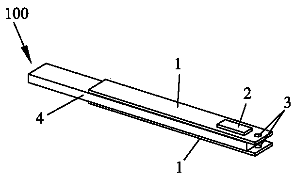
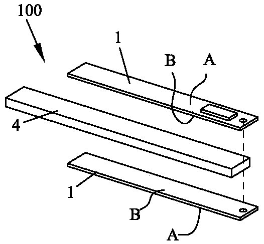
[0053] Please refer to figure 1 and figure 2 As shown, it shows the specific structure of the LED lamp 100 of the preferred embodiment of the present invention, which is a super heat dissipation LED lamp, which can be used in the fields of household environment lighting, automobile lamps, street lamps and the like.

[0054]Wherein, the structure of the LED lamp 100 includes two PCB components and a heat pipe 4 interposed therebetween. The PCB assembly is composed of a PCB 1 and a light-emitting element 2. The PCB 1 has a side A and a side B. The light-emitting element 2 is patch-welded on the A-side of the PCB 1, and the B-side is welded on the heat pipe 4. In this embodiment, the light-emitting element 2 is composed of a plurality of patch-type LED lamp beads. The heat pipe 4 is a vacuum copper pipe. The head end of the PCB 1 protrudes from the front end of the heat pipe 4 , and a positioning hole 3 is provided on the head end of the PCB 1 . The PCB1 is shorter than the ...


PUM

PropertyMeasurementUnit
melting pointaaaaaaaaaa

Abstract

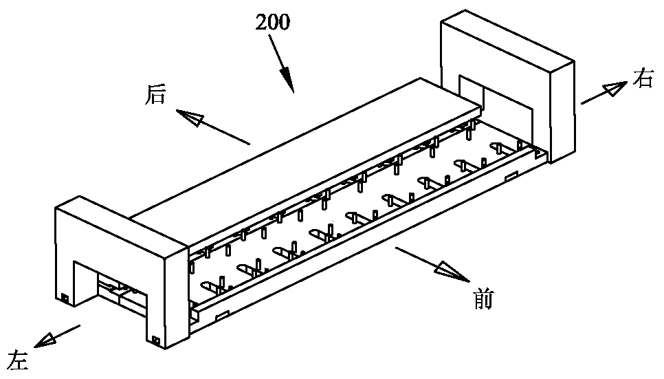
The invention discloses an LED lamp production process and an LED lamp welding jig. The welding jig comprises a pre-positioning bearing plate, a PCB positioning block, a bottom heat dissipation supporting plate, a top heat dissipation pressing plate, a left fixed lifting handle and a right fixed lifting handle. The pre-positioning bearing plate is designed in a splicing mode, the pre-positioning bearing plate, the PCB positioning block and the bottom heat dissipation supporting plate are spliced together at first to form an integral bottom assembly, after a product to be welded is loaded and the top heat dissipation pressing plate is pressed, the left fixed lifting handle and the right fixed lifting handle are clamped on the two sides of the PCB positioning block and the bottom heat dissipation supporting plate, the pre-positioning bearing plate falls automatically in the upward lifting process, accordingly, most of the product to be welded is exposed, hot air can be directly utilizedfor heat transfer during furnace welding, and the welding efficiency is high. By adopting the novel welding jig in the process, the production efficiency is improved, the good bubble rate between a light emitting element and a PCB is smaller than 5%, and the product quality is improved.

Description

technical field [0001] The invention relates to the technology in the field of lamps, in particular to a production process of an LED lamp and a welding fixture thereof. Background technique [0002] The Chinese invention patent with the patent number of 201710720364.0 discloses a welding process and fixture between heat pipe and PCB. This kind of fixture is provided with at least one slot on the base, and the slots are arranged on the base. The components to be welded are placed in the slot Among them, the inside of the slot is close to the two opposite first sides of the component to be welded. The component to be welded is formed by pasting the heat pipe and the PCB, and the first side is parallel to the bonding surface of the heat pipe and the PCB. In addition, the soldering fixture between the heat pipe and the PCB also includes an upper cover, the upper cover is buckled with the base, and is used to clamp the two second sides opposite to the component to be welded, and...

Claims


Application Information

Patent Timeline
Patent Type & Authority Applications(China)
IPC IPC(8): B23K1/008B23K1/08B23K3/08
CPCB23K1/008B23K1/08B23K3/085B23K3/087
Inventor 谭红平
Owner HUIZHOU HONGRUI PHOTOELECTRIC TECH CO LTD
Learn More