
A kind of metal sheet metal parts image mirrorless processing method

A technology of metal sheet metal parts and processing methods, which is applied in the field of metal sheet metal parts manufacturing, can solve problems such as the inability to form parts with steep side walls, the inability of materials to flow, and the excessive thinning of sheet metal, etc., to achieve rapid response to market demand, Satisfy the product innovation design requirements, the effect of good forming precision

Active Publication Date: 2020-03-27
深圳未来技术软件有限公司
View PDF4 Cites 0 Cited by
  • Summary
  • Abstract
  • Description
  • Claims
  • Application Information

AI Technical Summary

Problems solved by technology

[0005] However, in the existing NC incremental forming process, the sheet material undergoes progressive thinning and drawing deformation during the forming process, resulting in a thinning of the sheet material thickness, and the wall thickness of the formed part is constrained by the sinusoidal law (ie In the formula, t is the thickness of the sheet after forming, t 0 is the sheet thickness before forming, is the angle between the forming surface of the sheet metal and the vertical direction, called the semi-cone angle), and it is impossible to form a steep side wall with uniform wall thickness.
In addition, according to the previous incremental forming process of sheet metal, the surrounding of the sheet metal is fixed by the pressure plate during processing, and the material cannot flow. When processing parts with large forming angles, the sheet metal will be excessively thinned or even cracked.

Method used


Image

  • A kind of metal sheet metal parts image mirrorless processing method
  • A kind of metal sheet metal parts image mirrorless processing method
  • A kind of metal sheet metal parts image mirrorless processing method

Examples


Embodiment

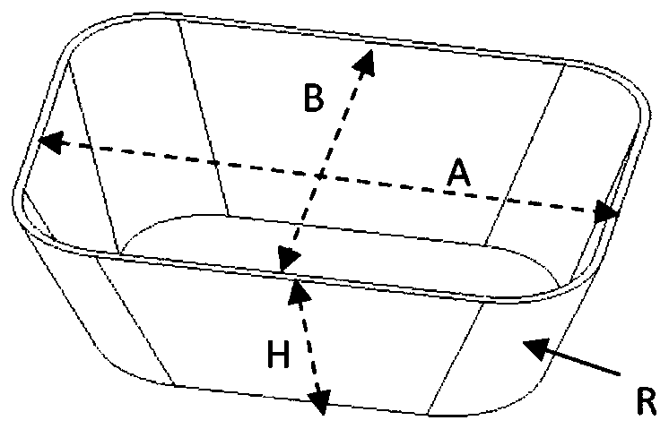
[0021] In this embodiment, the workpiece to be formed is a square box with inclined walls, and the specific shape is as follows: figure 1 As shown, the opening length is represented by A, the width is represented by B, the sidewall fillet radius is represented by R, and the height is represented by H.

[0022] The mirror image processing method of metal sheet metal parts of the present embodiment includes the following steps:

[0023] first step, such as image 3 As shown, the four boundaries of the rectangular sheet are fixed on the forming machine tool through the flexible fixture 1, and the two diagonals of the sheet divide the sheet into four areas, which are respectively marked as I and II in the figure , III, and IV areas, the flexible clamp 1 can adjust the clamping force.

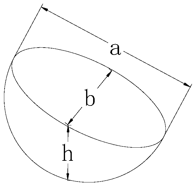
[0024] The second step is to build a figure 2 An intermediate configuration in the shape of a semi-ellipsoid is shown, the two equatorial radii (major and minor axes) of the semi-ellipsoid are h...


PUM


Abstract

The invention relates to a metal sheet metal part mirror image free mold machining method. The method comprises the following steps that 1, a rectangular plate material is fixed on a forming machine tool, and the two diagonal lines of the plate material divide the plate material into four regions; 2, a middle configuration is formed through a single forming tool for a first process, and the surface area of the middle configuration is 40-60% of the surface area of the final metal sheet metal part; when the tool head of the forming tool moves to a certain region of the plate material, the clamping force of a flexible clamp corresponding to the area plate material is reduced; and 3, the two forming tools are used for carrying out mirror image free mold forming on the plate materials at the same time and a final shape is formed for a second process, and the tool head of the lower forming tool is always located in the normal direction of the contact point of the tool head and the plate material. According to the method, a special mold is not needed, the machining period is short, the innovation design requirements of modern social products can be met, and the method has a good development prospect in the fields of rapid prototyping manufacture and new vehicle model exploitation.

Description

technical field [0001] The invention relates to a method for processing a mirror image of a metal sheet metal part without a mold, and belongs to the technical field of manufacturing the metal sheet metal part. Background technique [0002] Sheet metal products processed by sheet metal technology have been widely used in the automotive industry, aerospace, medical equipment, daily hardware and other industries due to their high strength, light weight, low cost, and the ability to achieve large-scale production. [0003] In recent years, with the rapid development of the national economy, modern society requires increasingly diversified and individualized products, continuous innovation in product design, and accelerated replacement. In this environment, product production has tended to develop towards small batches and multiple varieties, while the traditional stamping process has lost its advantages in the production of personalized products due to the constraints of long m...

Claims


Application Information

Patent Timeline
Patent Type & Authority Patents(China)
IPC IPC(8): B21D31/00
CPCB21D31/005
Inventor 鲍益东刘秀金霞王珉陈文亮王辉张得礼丁力平齐振超
Owner 深圳未来技术软件有限公司
Learn More