
Self-resetting rocking wall with buckling-constrained shape memory alloy bars and building

A technology of memory alloy and buckling constraint, which is applied in the direction of architecture, building types, building components, etc., and can solve problems such as easy buckling, high stiffness, and complex construction technology

Active Publication Date: 2018-12-04
SHANDONG UNIV
View PDF6 Cites 5 Cited by
  • Summary
  • Abstract
  • Description
  • Claims
  • Application Information

AI Technical Summary

Problems solved by technology

[0004] In order to overcome the complex structure and construction process of the existing prestressed self-resetting rocking wall, the rigidity after nominal yield is relatively large, the allowable deformation is limited, and the shape memory alloy components of the existing shape memory alloy self-resetting rocking wall are easy to buckle under pressure and fail. Fracture occurs, and it is easy to lose the initial stiffness under large earthquakes and low temperatures; the invention provides a self-resetting rocking wall based on buckling-constrained shape memory alloy rods; the self-resetting rocking wall has good energy dissipation under earthquake loads Performance and self-resetting ability, large allowable deformation range, symmetrical reciprocating load behavior, and will not lose initial stiffness at low temperature or after excessive deformation; damage control is achieved, structural beam members will not be damaged after an earthquake, and only the shape memory alloy needs to be replaced Function can be restored by removing the damper between the rod and the wall

Method used


Image

  • Self-resetting rocking wall with buckling-constrained shape memory alloy bars and building
  • Self-resetting rocking wall with buckling-constrained shape memory alloy bars and building
  • Self-resetting rocking wall with buckling-constrained shape memory alloy bars and building

Examples


Embodiment Construction

[0041] It should be pointed out that the following detailed description is exemplary and intended to provide further explanation to the present application. Unless defined otherwise, all technical and scientific terms used herein have the same meaning as commonly understood by one of ordinary skill in the art to which this application belongs.

[0042] It should be noted that the terminology used here is only for describing specific implementations, and is not intended to limit the exemplary implementations according to the present application. As used herein, unless the context clearly dictates otherwise, the singular is intended to include the plural, and it should also be understood that when the terms "comprising" and / or "comprising" are used in this specification, they mean There are features, steps, operations, means, components and / or combinations thereof;

[0043] For the convenience of description, if the words "up", "down", "left" and "right" appear in the present i...


PUM


Abstract

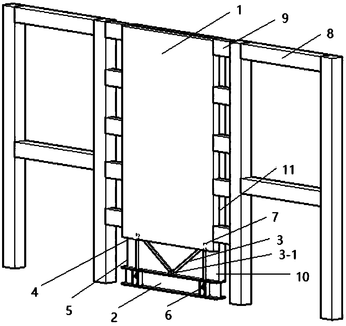
The invention discloses a self-resetting rocking wall based on buckling-constrained shape memory alloy bars. A rocking wall body and a foundation beam are connected by wall connecting systems, and thewall connecting systems ensure that the wall body and the foundation beam are directly hinged and leave sufficient rotating space for the rocking wall body. The alloy bars are arranged between the rocking wall body and the foundation beam, the bottoms of the alloy bars are connected to the foundation beam through anchoring devices, and the tops of the alloy bars are connected to the rocking wallbody through pre-embedded sleeves. Constraining sleeves are mounted on the circumferential sides of the shape memory alloy bars and wrap the shape memory alloy bars. Main body frames or walls are disposed on both sides of the rocking wall body, and the main body frames or the walls are connected with the rocking wall body through a plurality of sets of inter-wall dampers. The inter-wall dampers can improve the energy dissipation capability of the rocking wall. When the inter-wall dampers do not have the self-resetting performance, the shape memory alloy bars apply pre-tightening force in an over-thread-screwing mode to overcome the return resistance of the dampers.

Description

technical field [0001] The invention relates to the field of building steel structures, in particular to a self-resetting rocking wall containing buckling-constrained shape memory alloy rods and a steel structure building comprising the self-resetting rocking wall. Background technique [0002] The seismic design of buildings has gone through several stages such as rigid design, flexible design and ductility design. Because the ductility design can reduce the construction cost of anti-seismic structures and improve the anti-seismic performance of buildings to a certain extent, it has been widely used. However, the ductility design often means that the damage of the structure increases, and it is not easy to control the earthquake damage mode of the structure, which greatly increases the repair cost and difficulty of the building after the earthquake. Early studies have shown that properly loosening the connection between components and foundations and allowing the building ...

Claims


Application Information

Patent Timeline
IPC IPC(8): E04B2/00E04B1/98E04H9/02E04B1/00
CPCE04B1/00E04B2/00E04H9/02
Inventor 邱灿星张邑尘齐健陈城
Owner SHANDONG UNIV
Learn More