
Super-continuum spectrum generation device

A supercontinuum and generation device technology, applied in laser components, optics, instruments, etc., can solve the problems of optical isolator and optical fiber breakdown, limited utilization of pump light source, high professional requirements of lasers, etc., and achieve suppression of pulse energy , Suppress multi-mode generation, reduce the effect of nonlinear effects

Pending Publication Date: 2018-11-30
NAT UNIV OF DEFENSE TECH
View PDF6 Cites 3 Cited by
  • Summary
  • Abstract
  • Description
  • Claims
  • Application Information

AI Technical Summary

Problems solved by technology

The amplifier construction process involves welding between various devices and between devices and optical fibers, which is cumbersome and expensive; and the use of pumping and amplifying seed pulse lasers has limited utilization of the pump light source, and the common optical-optical efficiency It is only about 60%, and the electro-optical efficiency is only about 50%, so there is a large energy loss; according to the required amplification value, it is necessary to change the device and fiber parameters in the amplifier to match the amplification power, otherwise in The process of amplifying and generating high peak power pulses is likely to cause breakdown or burning of optical isolators and optical fibers in the amplifier, and modifying the amplifier is also a cumbersome task, which requires high professional requirements for laser users and is difficult to popularize

Method used


Image

  • Super-continuum spectrum generation device
  • Super-continuum spectrum generation device
  • Super-continuum spectrum generation device

Examples


Embodiment Construction

[0032] The present invention will be further described below with reference to the accompanying drawings and specific embodiments.

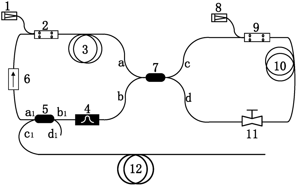
[0033] figure 1 It is a schematic diagram of the structure of the present invention. The present invention consists of a high peak power dissipation soliton resonance mode locking laser and a photonic crystal fiber 12 . The output of the high peak power dissipation soliton resonance mode-locked laser is connected to the photonic crystal fiber 12 .

[0034] The high peak power dissipation soliton resonance mode-locked laser is composed of a first pump source 1, a first wavelength division multiplexer 2, a first gain fiber 3, a filter 4, a second coupler 5, a polarization independent isolator 6, a first A coupler 7, a second pump source 8, a second wavelength division multiplexer 9, a second gain fiber 10, and a polarization controller 11. The components are connected in the following order to form two loops for high peak power dissipation Solit...


PUM


Abstract

The invention discloses a super-continuum spectrum generation device. The super-continuum spectrum generation device comprises a high-peak power consumption soliton resonant mode-locked laser and a photonic crystal fiber, wherein the high-peak power consumption soliton resonant mode-locked laser comprises two pumping light sources, two beam combiners, two gain fibers, a filter, a polarization irrelevant isolator and a polarization controller, the first pumping source, a pumping input arm of a first beam combiner, the first gain fiber, an input arm a and an output arm b of a first coupler, thefilter, an input arm b1 and an output arm a1 of a second coupler, the polarization irrelevant isolator and a signal input arm of the first beam combiner are connected to form a single-way ring, an output arm c1 of the second coupler is connected with the photonic crystal fiber, and an output end c of the first coupler is connected with the second beam combiner, a second gain fiber, the polarization controller and an output arm d of the first coupler to form a non-linear amplification annular mirror. By the super-continuum spectrum generation device, the power can be increased to several kilowatt magnitudes, and the super-continuum spectrum generation device is small in energy loss and long in fiber length.

Description

technical field [0001] The invention relates to a generating device of a supercontinuum, in particular to a generating device which can directly generate a spectrally stable supercontinuum without an amplifier. Background technique [0002] The supercontinuum light source has the advantages of wide spectrum, high brightness and good spatial coherence at the same time, so it has a wide range of applications in optical measurement, molecular spectroscopy, biomedical imaging and optical biological tissue erosion, and is a research hotspot in the field of light sources one. At present, the supercontinuum is mainly obtained by inputting pulsed laser into a photonic crystal fiber for nonlinear broadening. Since the degree of nonlinear broadening of the supercontinuum in photonic crystals is directly related to the peak power of the pulse, in order to obtain a supercontinuum light source with a wide spectral range and good stability, a pulsed laser with high peak power and stable ...

Claims


Application Information

Patent Timeline
Patent Type & Authority Applications(China)
IPC IPC(8): H01S3/067H01S3/098
CPCH01S3/06708H01S3/06712H01S3/06725H01S3/06741H01S3/06783H01S3/1106G02F1/3528
Inventor 徐荷陈胜平蔡君豪侯静姜宗福
Owner NAT UNIV OF DEFENSE TECH
Learn More