


Quick Research
Generate reliable direction feasibility study reports for your R&D in just a few steps.

Technical Q&A
Discover and master advanced knowledge NOW. Basics, ideas, possibilities, all at once.

Find Solutions
As an expert in R&D theories, this can generate solutions to your technical problems instantly.

Evaluate Feasibility
Analyze your overall solution with one click, know your potential R&D risks in advance.

Monitor Landscape
Get weekly tech updates, stay abreast of the latest tech innovations and key insights.
Pyrolysis gas treatment device and treatment method in process of tar production by pulverized coal pyrolysis
A processing device and pyrolysis gas technology, applied in coke ovens, gas dust removal, petroleum industry, etc., can solve the problems of large filter structure, low linear velocity, damage to the flow state of the filter bed, etc., to prevent blockage , the effect of prolonging the dressing cycle and increasing the area
- Summary
- Abstract
- Description
- Claims
- Application Information
AI Technical Summary
Problems solved by technology
Method used
Image

Examples
Embodiment 1
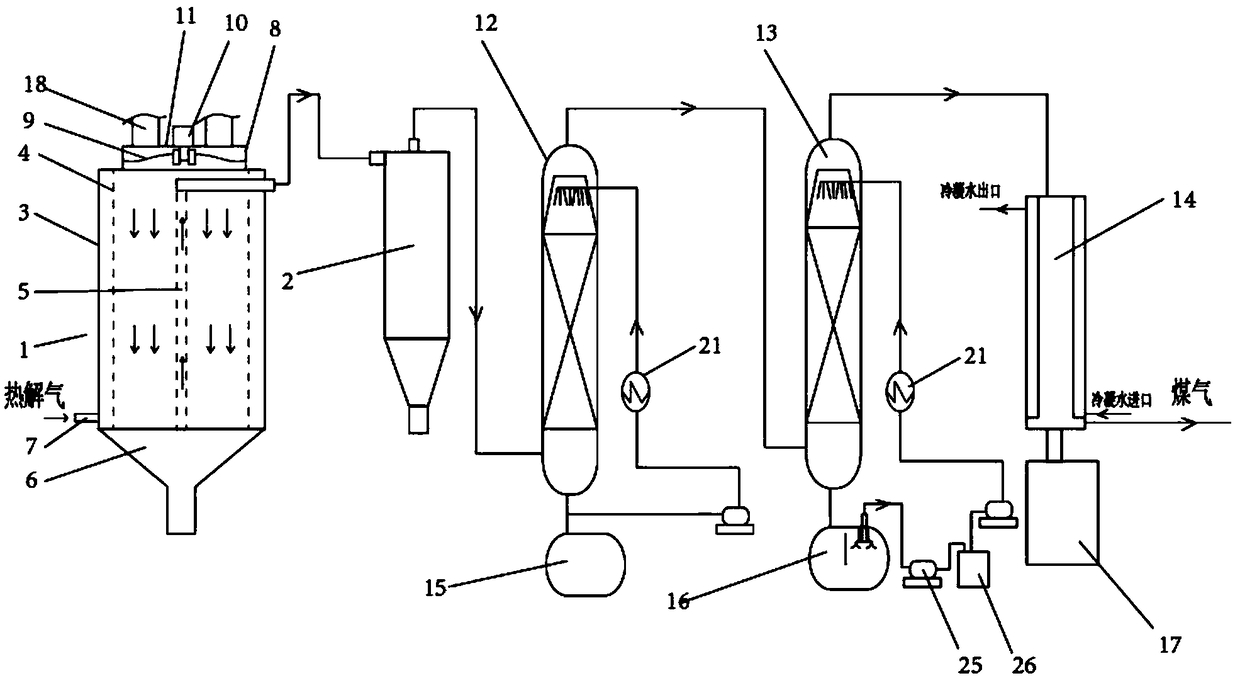
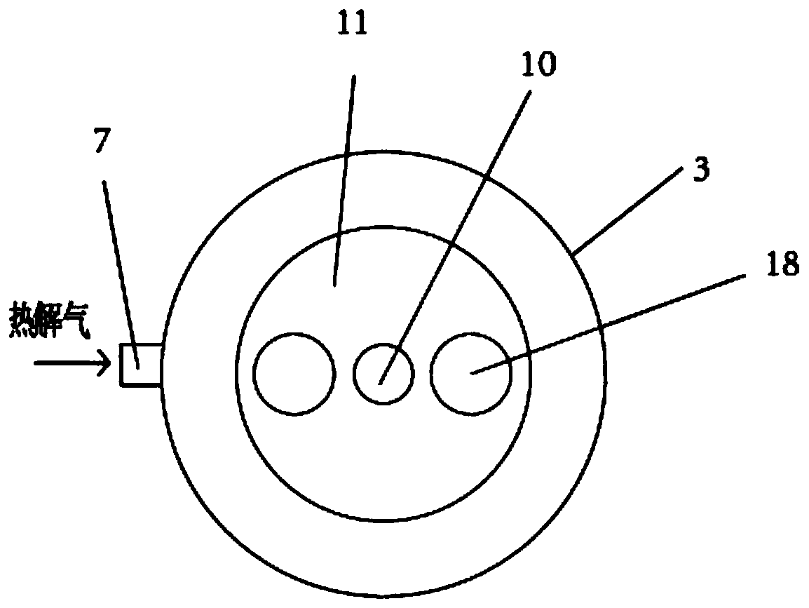
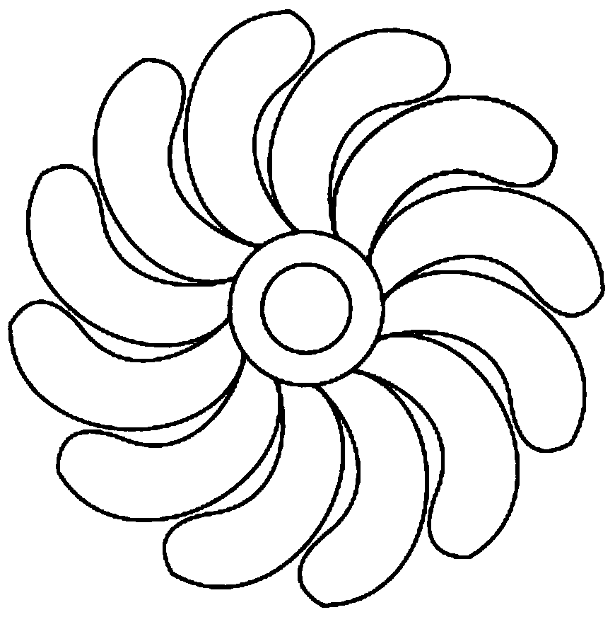
[0050] figure 1 Schematic diagram of the structure of the pyrolysis gas treatment device in the process of producing tar by pyrolysis of pulverized coal provided by the embodiment of the present invention; figure 2 The top view of the semi-coke filter of the pyrolysis gas treatment device in the pulverized coal pyrolysis tar production process provided by the embodiment of the present invention; image 3 Schematic diagram of the structure of the dispersing fan of the pyrolysis gas treatment device in the pulverized coal pyrolysis tar production process provided by the embodiment of the present invention; Figure 4 Schematic diagram of the structure of the internal pipe network or the external pipe network of the pyrolysis gas treatment device in the pulverized coal pyrolysis tar production process provided by the embodiment of the present invention; Figure 5 for Figure 4 The schematic diagram of the longitudinal section; Figure 6 Schematic diagram of the structure of th...
Embodiment 2
[0063] The pulverized coal with a particle size of 0-7mm is pyrolyzed at 600°C, and the pyrolysis gas treatment method during the pyrolysis process includes the following steps:
[0064] (1) The pyrolysis gas produced by pyrolysis of pulverized coal first enters the outer casing through the pyrolysis gas inlet of the semi-coke filter, and then enters between the outer pipe network and the inner pipe network through the outer pipe network. At the same time, The semi-coke is dropped from the semi-coke distribution feeding mechanism between the outer pipe network and the inner pipe network, and the pyrolysis gas and the semi-coke are in contact with each other. The temperature of the semi-coke is 450-800 ° C, and the temperature of the semi-coke filter is 500 ° C Left and right, the dust in the pyrolysis gas is preliminarily removed, and the removed powder coke is used as a semi-coke product along with the semi-coke, and the pyrolysis gas after the preliminary dust removal is disc...
Embodiment 3
[0069] The pulverized coal with a particle size of 0.3-3mm is pyrolyzed at 600°C, and the pyrolysis gas treatment method during the pyrolysis process includes the following steps:
[0070] (1) The pyrolysis gas produced by pyrolysis of pulverized coal first enters the outer casing through the pyrolysis gas inlet of the semi-coke filter, and then enters between the outer pipe network and the inner pipe network through the outer pipe network. At the same time, The semi-coke is dropped from the semi-coke distribution feeding mechanism between the outer pipe network and the inner pipe network, and the pyrolysis gas and the semi-coke are in contact with each other. The temperature of the semi-coke is 450-800 ° C, and the temperature of the semi-coke filter is 500 ° C Left and right, the dust in the pyrolysis gas is preliminarily removed, and the removed powder coke is used as a semi-coke product along with the semi-coke, and the pyrolysis gas after the preliminary dust removal is di...
PUM
 Abstract
Description
Claims
Application Information
 - R&D Engineer
- R&D Manager
- IP Professional
- Industry Leading Data Capabilities
- Powerful AI technology
- Patent DNA Extraction
Browse by: Latest US Patents, China's latest patents, Technical Efficacy Thesaurus, Application Domain, Technology Topic, Popular Technical Reports.
© 2024 PatSnap. All rights reserved.Legal|Privacy policy|Modern Slavery Act Transparency Statement|Sitemap|About US| Contact US: help@patsnap.com