Fully-automatic molding sand production system and method for precision casting
A precision casting and production system technology, applied in the field of casting production, can solve the problems of mold sand transfer and low automation of upper mold processing, and achieve the effects of reducing impact force, production cost and distance
- Summary
- Abstract
- Description
- Claims
- Application Information
AI Technical Summary
Problems solved by technology
Method used
Image

Examples
Embodiment 1
[0046]Embodiments of the present invention are described in detail below, examples of which are shown in the drawings, wherein the same or similar reference numerals designate the same or similar elements or elements having the same or similar functions throughout. The embodiments described below by referring to the figures are exemplary and are intended to explain the present invention and should not be construed as limiting the present invention.
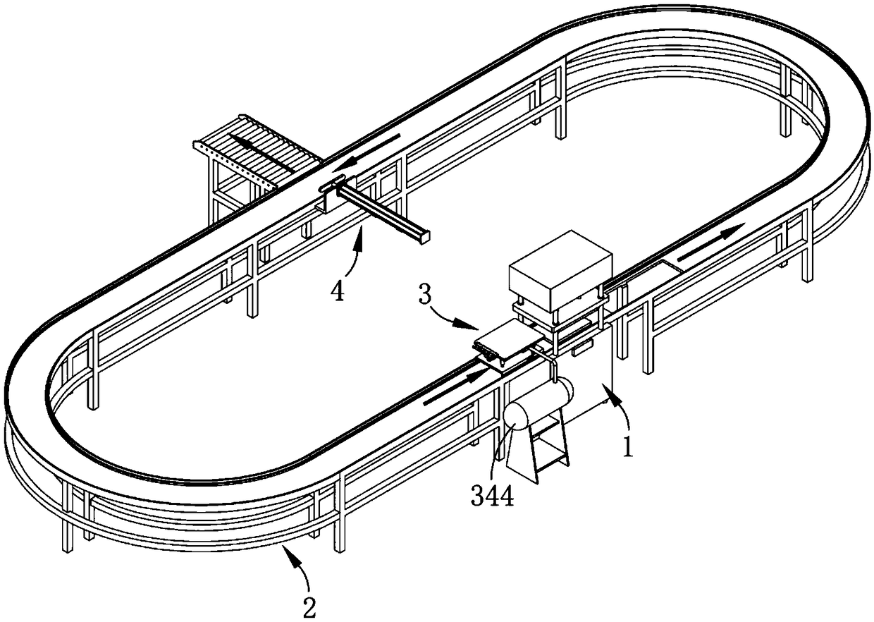
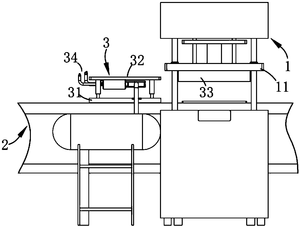
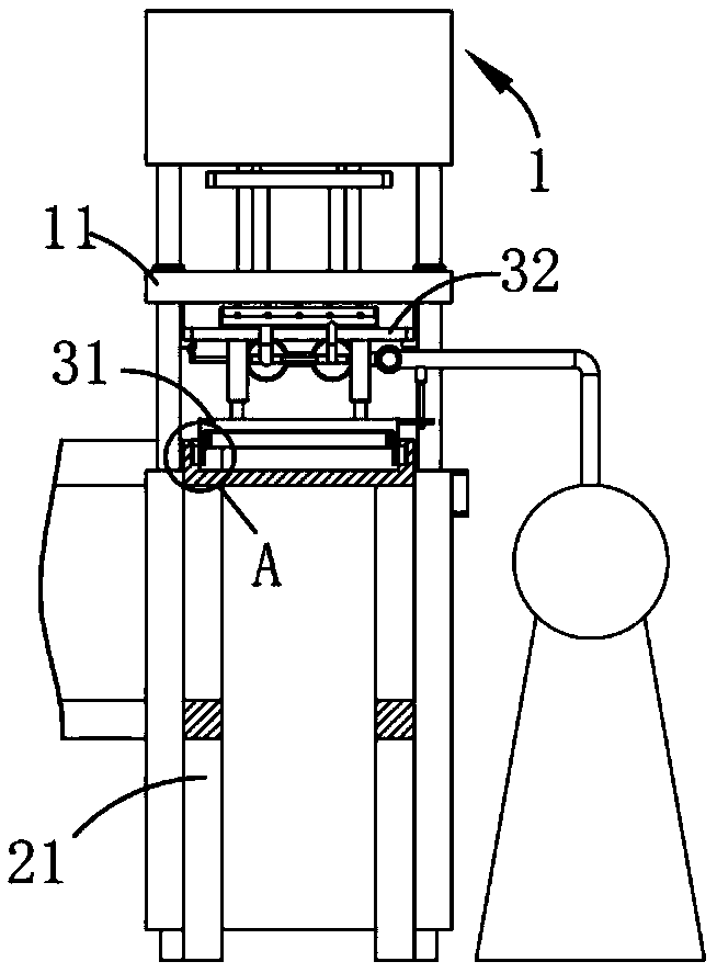
[0047] Such as figure 1 , 2 Shown in and 3, a kind of molding sand automatic production system for precision casting, comprises core shooter 1, also comprises:
[0048] Guide mechanism 2; in this embodiment, the mobile trolley 31 moves along the guide mechanism 2 to transfer the molding sand formed by the core shooter 1 to the output station;
[0049] A blanking mechanism 3, the blanking mechanism 3 includes a transfer trolley 31 moving along the guide mechanism 2, a material receiving assembly 32 arranged on the transfer trolle...
Embodiment 2
[0054] Such as figure 1 , 2 As shown in and 7, the parts identical or corresponding to those in the first embodiment adopt the reference numerals corresponding to the first embodiment. For the sake of simplicity, only the differences from the first embodiment are described below; The difference is that: the material receiving assembly 32 includes a plurality of guide posts 321 arranged vertically and parallel on the upper surface of the mobile trolley 31 , and a receiving portion 322 which is arranged in a sliding fit with the guide posts 321 and is in a horizontal state. And the elastic portion 323 arranged between the receiving portion 322 and the mobile trolley 31; in the present embodiment, the guide columns 321 are set in four, which are evenly distributed on the four corners of the mobile trolley 31, and are received by the guide columns. While the part 322 is limiting, the elastic part 323 is used to pull the receiving part 322 to improve the stability during its upwar...
Embodiment 3
[0059] Such as figure 1 , 2 , 7 and 9, the parts identical or corresponding to the second embodiment adopt the reference numerals corresponding to the second embodiment. For the sake of simplicity, only the differences from the first embodiment are described below; The difference between the two is that the finishing assembly 34 includes a cleaning part 341 for cleaning the inside of the upper mold 11, a spraying part 342 located on the side of the cleaning part 341 for spraying release agent on the cleaned upper mold 11, and The transmission assembly 33 is intermittently connected to control the spraying part 342 and the cleaning part 341 to intermittently perform air spraying and release agent spraying control part 343 and the air supply part 344 to supply airflow to the spraying part 342 and cleaning part 341 ; In the present embodiment, the finishing assembly 34 is fixedly arranged on the bottom of the receiving part 322, and the mobile trolley 31 drives the receiving par...
PUM
 Abstract
Description
Claims
Application Information
 - R&D
- Intellectual Property
- Life Sciences
- Materials
- Tech Scout
- Unparalleled Data Quality
- Higher Quality Content
- 60% Fewer Hallucinations
Browse by: Latest US Patents, China's latest patents, Technical Efficacy Thesaurus, Application Domain, Technology Topic, Popular Technical Reports.
© 2025 PatSnap. All rights reserved.Legal|Privacy policy|Modern Slavery Act Transparency Statement|Sitemap|About US| Contact US: help@patsnap.com