
Constant temperature fireproof power distribution cabinet

A power distribution cabinet and constant temperature technology, which is applied to the substation/power distribution device shell, electrical components, substation/switch layout details, etc., can solve the problems of prolonging the cooling time and effect of the power distribution cabinet, poor practicability, and poor efficiency. Improve the effect of cooling and heat dissipation operations, rapid heat dissipation operations, and simple structure

Inactive Publication Date: 2019-10-08
常德三欣电力电子科技有限公司
View PDF22 Cites 9 Cited by
  • Summary
  • Abstract
  • Description
  • Claims
  • Application Information

AI Technical Summary

Problems solved by technology

Existing patent No. CN108306186A discloses a fireproof power distribution cabinet. When the temperature inside the power distribution cabinet is too high, the first stepping motor drives the fan part and then drives the five fans to rotate. The extension of the cylinder drives five fans to move, and five third stepping motors drive five fans to complete heat dissipation, which can quickly lower the internal temperature of the distribution box, prevent fires, and effectively protect the power distribution Cabinet, although the invention can cool down the power distribution cabinet to achieve the protection effect, but its structure is relatively complicated, with multiple hydraulic cylinders and motors, and these devices will also generate heat during operation, thus prolonging the life of the power distribution cabinet. The cooling time and effect are poor, and the power distribution cabinet has a single function and poor practicability

Method used


Image

  • Constant temperature fireproof power distribution cabinet
  • Constant temperature fireproof power distribution cabinet
  • Constant temperature fireproof power distribution cabinet

Examples


Embodiment Construction

[0031] The technical solutions of the present invention will be clearly and completely described below in conjunction with the accompanying drawings. Apparently, the described embodiments are some of the embodiments of the present invention, but not all of them.

[0032] The components of the embodiments of the invention generally described and shown in the figures herein may be arranged and designed in a variety of different configurations. Accordingly, the following detailed description of the embodiments of the invention provided in the accompanying drawings is not intended to limit the scope of the claimed invention, but merely represents selected embodiments of the invention.

[0033] Based on the embodiments of the present invention, all other embodiments obtained by persons of ordinary skill in the art without making creative efforts belong to the protection scope of the present invention.

[0034] In the description of the present invention, it should be noted that the t...


PUM


Abstract

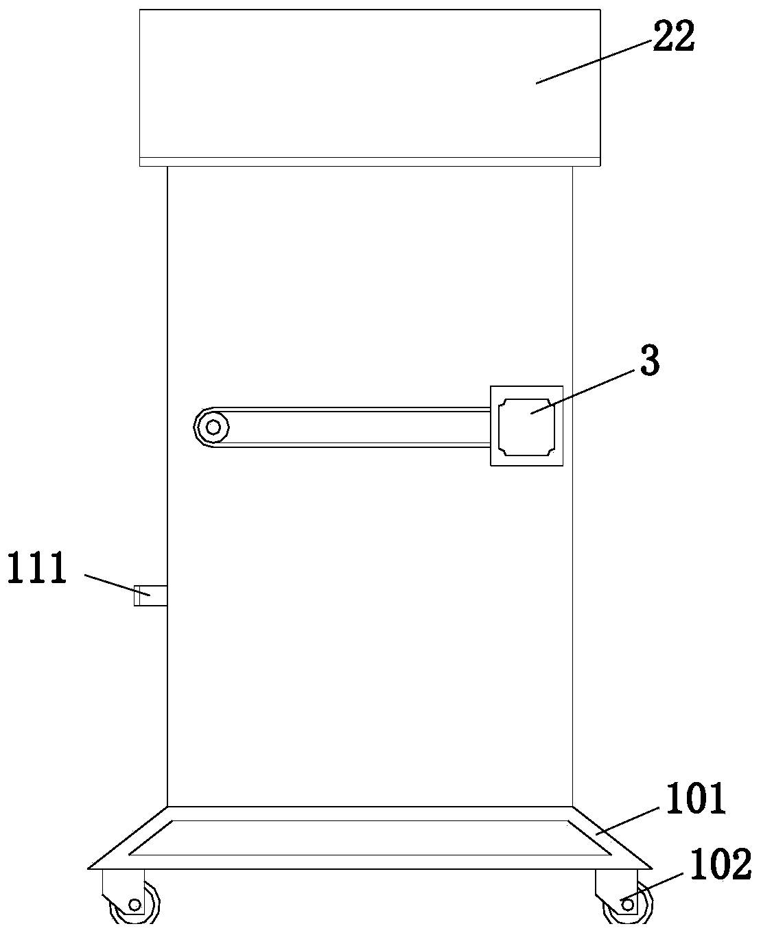
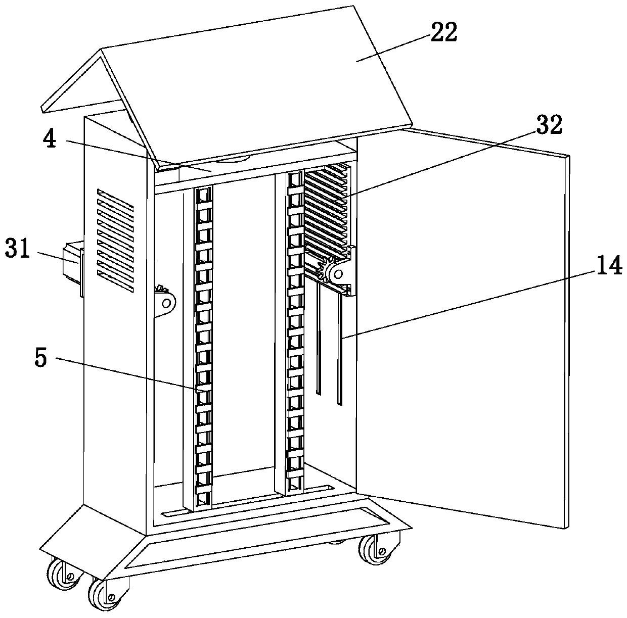
The invention discloses a constant temperature fireproof power distribution cabinet and belongs to the technical field of a power distribution cabinet. The constant temperature fireproof power distribution cabinet includes a cabinet body, a rotating mechanism, a heat radiation mechanism, a monitoring control mechanism and a wire harness mechanism, wherein a front side wall of the cabinet body is provided with a door plate matched with the cabinet body, the door plate is provided with a lock capable of being locked with the cabinet body, the door plate is provided with a protection assembly, the rotating mechanism is arranged at the top of the cabinet body, two side walls of the cabinet body are provided with multiple vent holes, the monitoring control cabinet is arranged at an upper portion in the cabinet body, the wire harness mechanism is vertically movably mounted in the cabinet body, a bottom wall and a side wall of the cabinet body are provided with a moving assembly and a handleassembly respectively, a top portion in the cabinet body is provided with an illumination lamp, and the rotating mechanism, the heat radiation mechanism and the illumination lamp are electrically connected with the monitoring control mechanism. The constant temperature fireproof power distribution cabinet is advantaged in that the structure is simple, rapid heat radiation operation of the whole cabinet can be realized, efficiency is relatively high, functions are various, and practicality is relatively strong.

Description

technical field [0001] The invention relates to the technical field of distribution boxes, in particular to a constant temperature and fireproof distribution cabinet. Background technique [0002] With the development of my country's economy, the goal of building a conservation-oriented society and sustainable development has deepened, and more and more attention has been paid to the standardized management of power construction, safe power consumption, and energy-saving power consumption. In recent years, a large amount of money has been invested in the construction and transformation of power grids. , and the power distribution cabinet is an important project of construction. Power distribution cabinet is a low-voltage power distribution device composed of switchgear, measuring instrument, protective device and auxiliary equipment in closed or semiclosed metal safe or on screen width according to the requirements of electrical wiring. Existing patent No. CN108306186A discl...

Claims


Application Information

Patent Timeline
IPC IPC(8): H02B1/56H02B1/28H02B1/30H02B1/32H02B1/20
CPCH02B1/20H02B1/28H02B1/303H02B1/32H02B1/565
Inventor 李铁琼王正群
Owner 常德三欣电力电子科技有限公司
Learn More