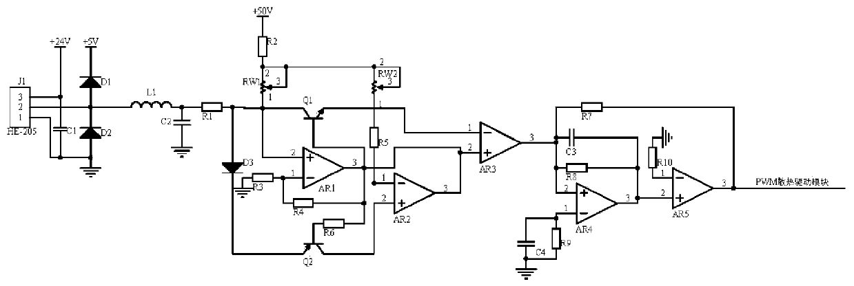
Power regulation circuit for motor cooling equipment of stamping robot
A technology for motor heat dissipation and power regulation, applied in the field of circuits, can solve the problems of insufficient heat dissipation, large PWM signal acquisition and drive error, and high temperature of stamping robots
- Summary
- Abstract
- Description
- Claims
- Application Information
AI Technical Summary
Problems solved by technology
Method used
Image
Examples
Embodiment 1
[0013] Embodiment 1, the power regulation circuit for the motor heat dissipation equipment of the stamping robot includes a temperature detection circuit, a voltage stabilization calibration circuit and a PWM signal conversion circuit. When the robot is working, the heating temperature of the servo motor is stabilized by two series-connected diodes D1 and D2, and the inductance L1 is connected in parallel with the capacitor C2 to filter out high-frequency interference, and then output a stable 0-5V voltage, which enters the voltage stabilization and calibration circuit. The voltage stabilization calibration circuit uses operational amplifier AR1, operational amplifier AR2, variable resistor RW1, and variable resistor RW2 to form a composite circuit to stabilize the signal voltage, and finally the operational amplifier AR3 is in-phase amplified and then input to the PWM signal conversion circuit. Transistor Q1 and triode Q2 have the effect of adjusting the output signal potentia...
Embodiment 2
[0015] Embodiment 2. On the basis of Embodiment 1, the temperature detection circuit selects the infrared temperature measuring probe J1 of model HE-205 to detect the heating temperature of the servo motor when the stamping robot is working in real time. D2 stabilizes the voltage, inductance L1 connects capacitor C2 in parallel to filter out high-frequency interference, and outputs a stable 0-5V voltage, which enters the voltage stabilization comparison circuit to stabilize the signal and improve the anti-interference performance of the signal. Infrared temperature measuring probe J1 The pin 3 of the infrared temperature measuring probe J1 and the upper end of the capacitor C1 are connected to the power supply +24V, the pin 1 of the infrared temperature measuring probe J1 and the lower end of the capacitor C1 are connected to the ground, and the pin 2 of the infrared temperature measuring probe J1 is respectively connected to the cathode of the diode D1 and the diode D2. The po...
Embodiment 3
[0016] Embodiment three, on the basis of embodiment one, the PWM signal conversion circuit uses operational amplifier AR4, operational amplifier AR5, capacitor C3, and capacitor C4 to form a composite conversion circuit to convert the voltage signal into a PWM signal. The signal output by the calibration circuit is an analog voltage signal, which cannot directly drive the PWM heat dissipation drive module to work. After the signal calibrated by the voltage stabilization calibration circuit stabilizes the signal amplitude, it can be composited by the operational amplifier AR5, capacitor C3, and capacitor C4. The conversion circuit converts the voltage signal into a PWM signal, and controls the PWM heat dissipation drive module built in the motor cooling equipment of the stamping robot to work; the non-inverting input terminal of the operational amplifier AR4 is connected to one end of the capacitor C3, the output terminal of the operational amplifier AR3 and the resistor R7 , On...
PUM
 Abstract
Description
Claims
Application Information
 - Generate Ideas
- Intellectual Property
- Life Sciences
- Materials
- Tech Scout
- Unparalleled Data Quality
- Higher Quality Content
- 60% Fewer Hallucinations
Browse by: Latest US Patents, China's latest patents, Technical Efficacy Thesaurus, Application Domain, Technology Topic, Popular Technical Reports.
© 2025 PatSnap. All rights reserved.Legal|Privacy policy|Modern Slavery Act Transparency Statement|Sitemap|About US| Contact US: help@patsnap.com


