Method for nano-imprinting based on centrifugal force, and prepared polymer micro-nano structure
A technology of nano-imprinting and micro-nano structure, which is applied in the photoplate-making process of pattern surface, photomechanical equipment, micro-lithography exposure equipment, etc., which can solve the problem of high cost and achieve low cost, simple process and wide applicability Effect
- Summary
- Abstract
- Description
- Claims
- Application Information
AI Technical Summary
Problems solved by technology
Method used
Image
Examples
Embodiment 1
[0077] The steps of the centrifugal force-based nanoimprint method described in this embodiment are as follows:
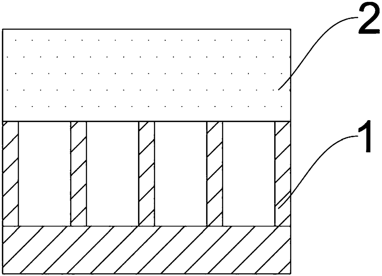
[0078] (1) Spin-coat the UV-curable photoresist (manufacturer: Obducat, model: STU220) on the porous alumina template with a spin-coating thickness of 0.2-2 μm, such as figure 1 shown;
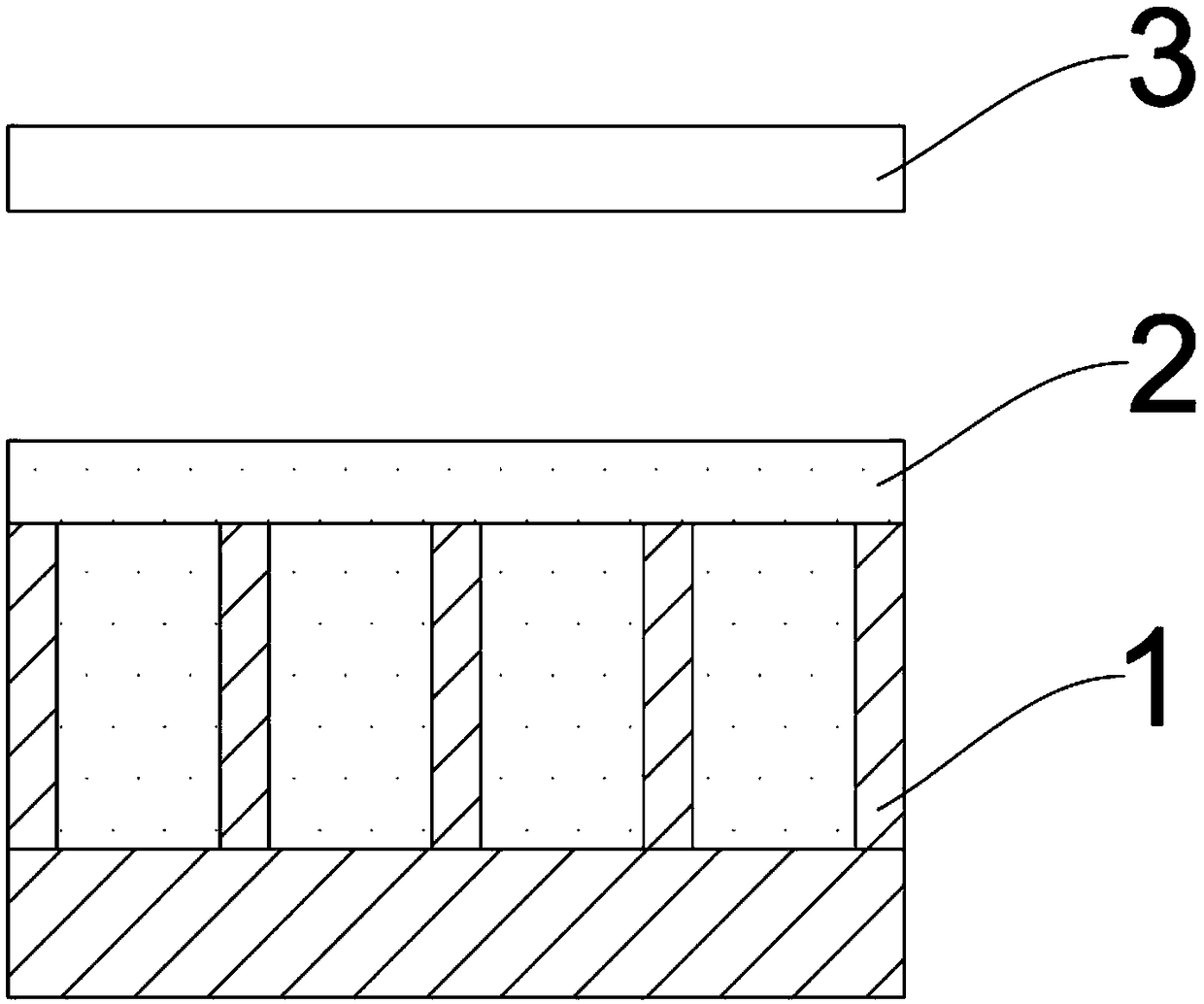
[0079] (2) Then place the porous alumina template spin-coated with polymer in a centrifuge device, heat up to 70°C; then, set the rotation speed at 8000rpm / min, keep the temperature for 10min, and then expose to ultraviolet light for 2min. figure 2 shown;
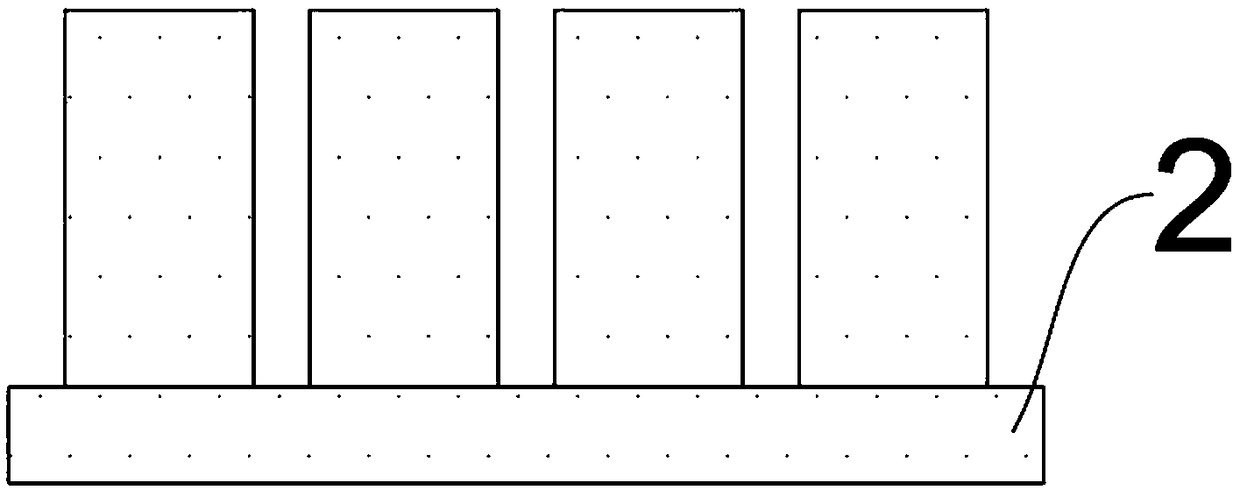
[0080] (3) After ultraviolet exposure, stop heating, turn off the centrifuge equipment, cool down to room temperature, dissolve and remove the porous alumina template with sodium hydroxide solution, and rinse and dry repeatedly with deionized water to obtain the micro-nano structure of the polymer—that is, polymerization Nanopillar array structures of objects, such as image 3 shown.
Embodiment 2
[0082] The steps of the centrifugal force-based nanoimprint method described in this embodiment are as follows:
[0083] (1) Spin-coat the UV-curable photoresist on the porous alumina template, and the spin-coating thickness is 2-5 μm;
[0084] (2) Then place the porous alumina template spin-coated with polymer in a centrifuge device, heat up to 55°C; then, set the rotation speed at 20000rpm / min, keep the temperature for 5min, and then expose to ultraviolet light for 2min;
[0085] (3) After ultraviolet exposure, stop heating, turn off the centrifuge equipment, cool down to room temperature, dissolve and remove the porous alumina template with sodium hydroxide solution, and rinse and dry repeatedly with deionized water to obtain the micro-nano structure of the polymer—that is, polymerization nanopillar array structure.
Embodiment 3
[0087] The steps of the centrifugal force-based nanoimprint method described in this embodiment are as follows:
[0088] (1) Spin-coat the UV-curable photoresist on the porous alumina template, and the spin-coating thickness is 0.2-2 μm;
[0089] (2) Then place the porous alumina template spin-coated with polymer in a centrifuge device, heat up to 85°C; then, set the rotation speed at 7000rpm / min, keep the temperature for 15min, and then expose to ultraviolet light for 2min;
[0090] (3) After ultraviolet exposure, stop heating, turn off the centrifuge equipment, cool down to room temperature, dissolve and remove the porous alumina template with sodium hydroxide solution, and rinse and dry repeatedly with deionized water to obtain the micro-nano structure of the polymer—that is, polymerization nanopillar array structure.
PUM
| Property | Measurement | Unit |
|---|---|---|
| thickness | aaaaa | aaaaa |
Abstract
Description
Claims
Application Information
 - R&D Engineer
- R&D Manager
- IP Professional
- Industry Leading Data Capabilities
- Powerful AI technology
- Patent DNA Extraction
Browse by: Latest US Patents, China's latest patents, Technical Efficacy Thesaurus, Application Domain, Technology Topic, Popular Technical Reports.
© 2024 PatSnap. All rights reserved.Legal|Privacy policy|Modern Slavery Act Transparency Statement|Sitemap|About US| Contact US: help@patsnap.com


