
Lightweight wire cutting machine

A wire cutting machine, lightweight technology, applied in work accessories, fine work devices, stone processing equipment, etc., can solve problems such as rack weight, achieve light rack structure, easy filling and removal, and prevent instability. Effect

Inactive Publication Date: 2018-11-23
ZHENGZHOU INSOLL TOOLS TECH CO LTD
View PDF9 Cites 4 Cited by
  • Summary
  • Abstract
  • Description
  • Claims
  • Application Information

AI Technical Summary

Problems solved by technology

[0003] The purpose of the present invention is to provide a lightweight wire cutting machine to solve the technical problem that the frame of the existing wire cutting machine is heavy

Method used


Image

  • Lightweight wire cutting machine
  • Lightweight wire cutting machine
  • Lightweight wire cutting machine

Examples


Embodiment 1

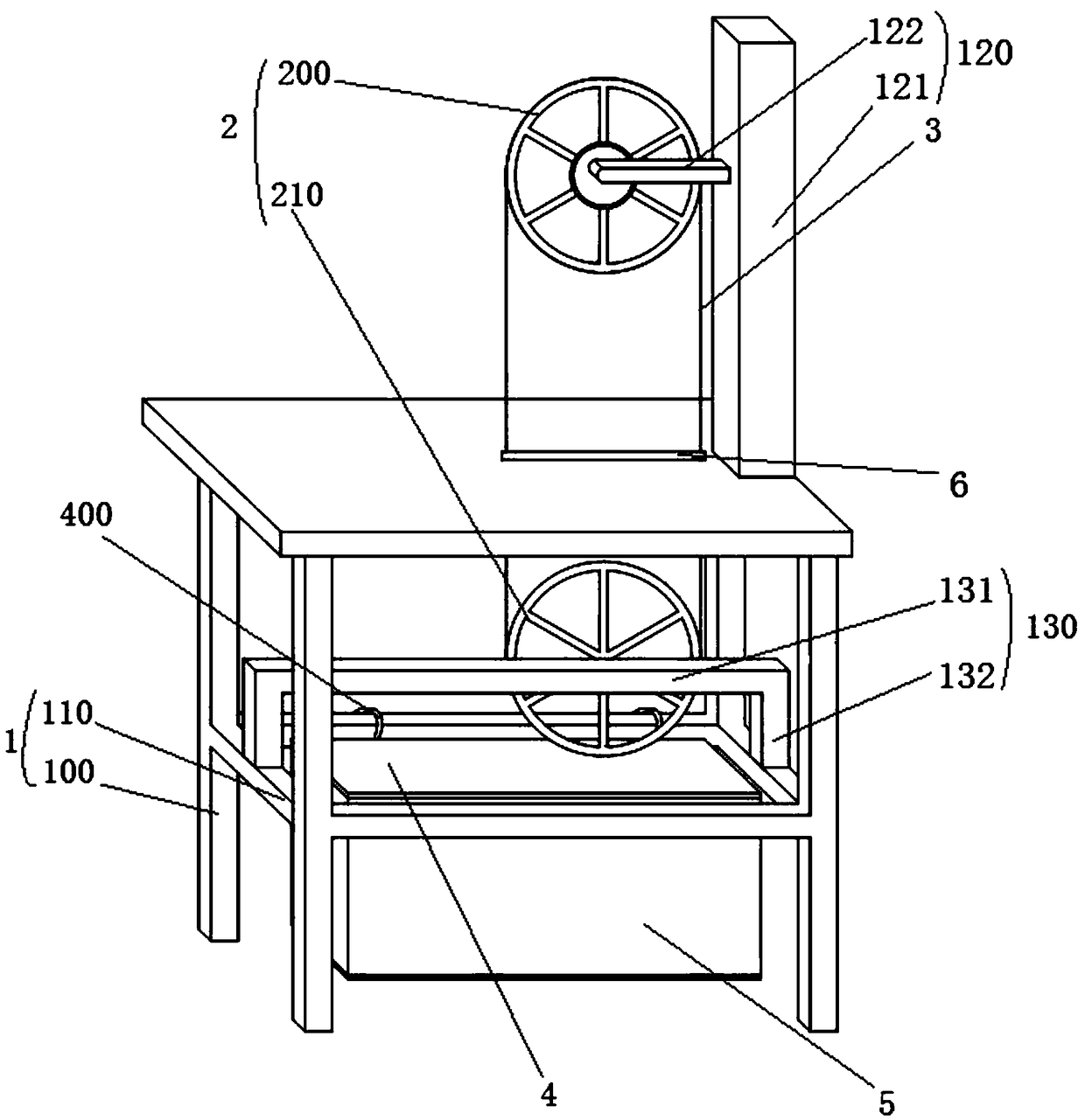
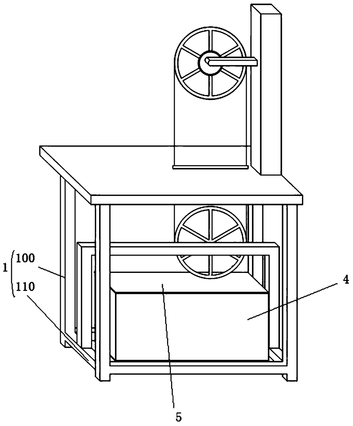
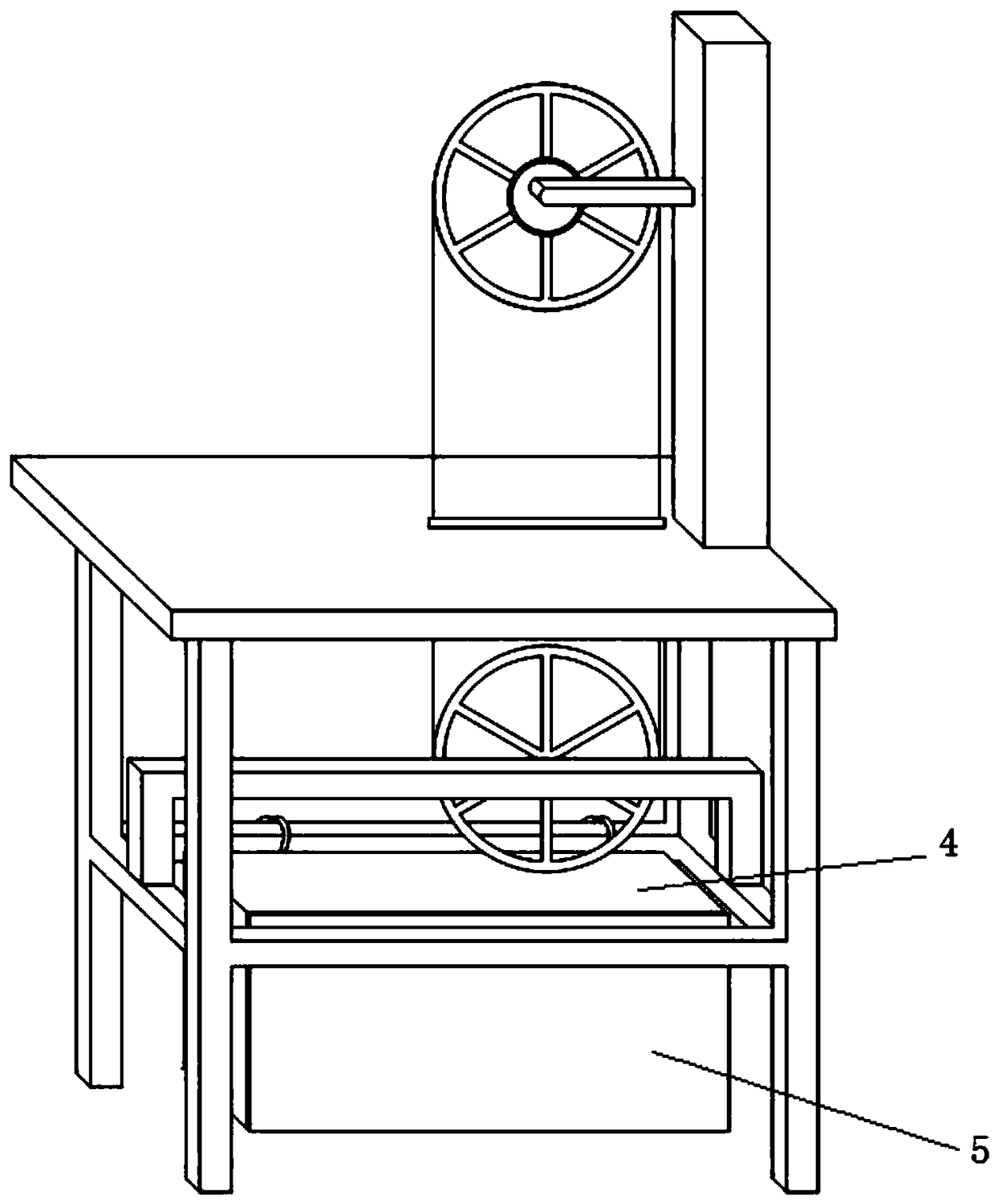
[0023] The light-weight wire cutting machine in this embodiment includes a frame 1 and a guide wheel 2 installed on the frame. There are two guide wheels, and the two guide wheels are respectively a driving wheel 200 and a driven wheel 210 . The driving wheel and the driven wheel are wound with a diamond wire saw 3 . The diamond wire saw 3 is an annular diamond wire saw. Frame 1 is assembled from lightweight materials. Lightweight material is aluminum profile. The frame includes a support frame and a working platform fixed on the top of the support frame. The driving wheel is located above the working platform, and the driven wheel is located below the working platform. The working platform is provided with a through hole 6 for the circular diamond wire saw to pass through. One through hole 6 is provided, and the through hole 6 is an elongated through hole for the two wires of the ring diamond wire saw to pass through. The upper part of the frame 1 is provided with an upp...

Embodiment 2

[0027] The general structure of the lightweight wire cutting machine described in this embodiment is consistent with that of Embodiment 1, but it is different from Embodiment 1 in that there are two through holes, and the two through holes are respectively set on the two wires of the diamond wire saw. place.

Embodiment 3

[0029] The general structure of the lightweight wire cutting machine described in this embodiment is consistent with that of Embodiment 1, but the difference from Embodiment 1 is that the frame is provided with two counterweight chambers for accommodating counterweights.


PUM


Abstract

The invention relates to a lightweight wire cutting machine. The lightweight wire cutting machine comprises a machine frame and two guide wheels installed on the machine frame, and the two guide wheels comprise the driving wheel and the driven wheel; a diamond wire saw is wound around the driving wheel and the driven wheel; the machine frame is formed by assembling lightweight materials; the machine frame comprises a supporting frame and a working platform fixed to the top of the supporting frame; the driving wheel and the driven wheel are located above the working platform and below the working platform respectively, and the working platform is provided with a through hole for the diamond wire saw to pass through; the machine frame is provided with one or two balance weight chambers for containing balance weights, and each balance weight chamber is composed of a bottom plate and side plates surrounding the bottom plate; the balance weight chambers are provided openings, and the openings are provided with door plates for closing the openings; the balance weight chambers are detachably connected with the machine frame, and the balance weight chambers are provided with fixing piecesfor fixing the balance weight chambers to the machine frame. The entire machine frame is light and easy to transport and move. The machine frame is provided with the multiple balance weight chambers,so that the operation stability of the lightweight wire cutting machine is improved.

Description

technical field [0001] The invention belongs to the technical field of wire cutting machines, and in particular relates to a lightweight wire cutting machine. Background technique [0002] At present, the tools used in the prior art for cutting hard and brittle materials (for example: single crystal silicon rods, gallium arsenide crystals, quartz glass, etc.) are inner circle or outer circle or circular diamond saw blades, which cut one kerf at a time. There is also a wire saw in the prior art, which is usually a linear metal wire. On the sawing device using this wire saw, a metal wire is often arranged in multiple groups, and multiple slits can be cut at one time, making multiple wires. A sheet of hard and brittle material. Use the existing wire saw to cut the sheet. During the operation, the wire saw is moved under the drive of the power device, and then the oil-soaked abrasive powder is sprinkled on the wire saw, and through the gap between the abrasive falling on the wi...

Claims


Application Information

Patent Timeline
IPC IPC(8): B28D5/04B28D7/00
CPCB28D5/0058B28D5/045
Inventor 陈富田董士杰陈金良
Owner ZHENGZHOU INSOLL TOOLS TECH CO LTD
Learn More