
Knife grinder

A knife sharpening machine and frame technology, which is applied in the directions of grinding machine parts, grinding workpiece supports, grinding drive devices, etc., can solve problems such as troublesome operation and reduce processing efficiency, and achieve improved processing efficiency and simplified process. Effect

Active Publication Date: 2018-11-16
重庆市开州区三中印务有限公司
View PDF8 Cites 9 Cited by
  • Summary
  • Abstract
  • Description
  • Claims
  • Application Information

AI Technical Summary

Problems solved by technology

The existing knife sharpening machine is simple in structure and easy to operate, but it also has the following defects: the existing knife sharpening machine can only grind the blade on one side of the circular blade at a time, and after grinding the single-sided blade of a circular blade, It is necessary to disassemble the round blade from the frame and turn over one side and then reinstall it, and then grind the blade on the other side, which is cumbersome to operate and reduces the processing efficiency

Method used


Image

  • Knife grinder

Examples


Embodiment Construction

[0015] The following is further described in detail through specific implementation methods:

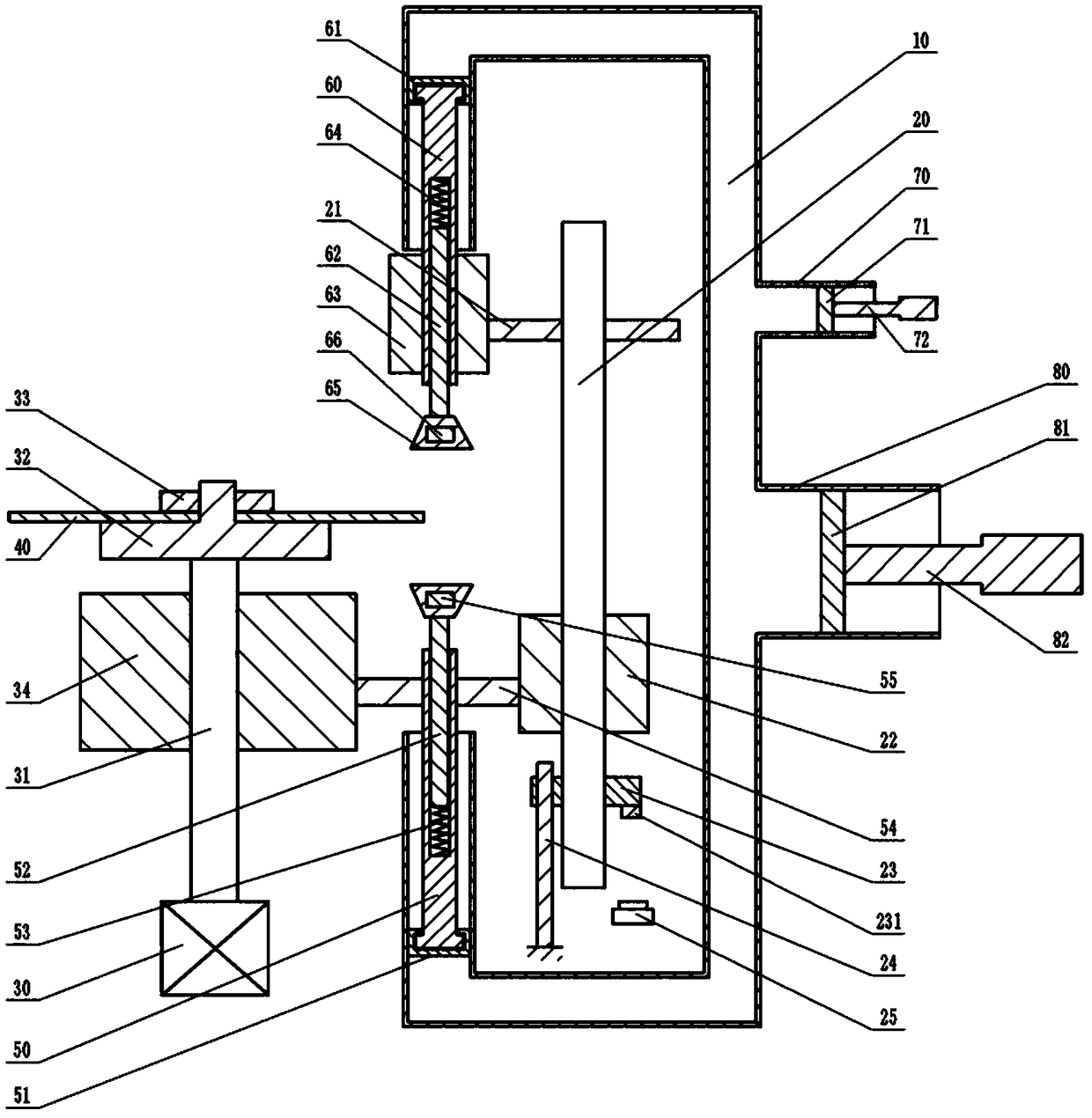
[0016] Instructions attached figure 1 The reference signs in include: connecting column 10, transmission shaft 20, output gear 21, second gear cylinder 22, nut 23, pressure block 231, limit rod 24, single control switch 25, motor 30, rotating shaft 31, mounting seat 32. Positioning block 33, third gear cylinder 34, circular blade 40, second plunger 50, second piston 51, second push rod 52, second extension spring 53, first gear 54, electromagnet 55, first Plunger 60, first piston 61, first push rod 62, first gear cylinder 63, first tension spring 64, grinding wheel 65, magnet 66, second annular cylinder 70, second pressure plate 71, second handle 72, the first An annular cylinder 80 , a first pressing plate 81 , and a first handle 82 .

[0017] Such as figure 1 As shown, the knife grinder includes a frame, a grinding unit, a transmission unit, a control unit and a clamping unit, a...


PUM


Abstract

The invention belongs to the technical field of knife grinding devices, and particularly discloses a knife grinder which comprises a frame, a grinding unit, a transmission unit and a clamping unit. The clamping unit comprises a mounting seat, a rotating shaft and a motor, the grinding unit comprises a communication column and an adjusting mechanism, a first piston is slidably connected in one sideof the communication column, a first plunger piston is rotatably connected on the first piston, a second piston is slidably connected in the other side of the communication column, a second plunger piston is rotatably connected on the second piston, grinding wheels are fixed onto the first plunger piston and the second plunger piston, a first gear cylinder is fixed onto the first plunger piston,a first gear is fixed onto the second plunger piston, the transmission unit comprises a transmission shaft rotatably connected on the frame, an output gear and a second gear cylinder are fixed onto the transmission shaft, the output gear is engaged with the first gear cylinder, the second gear cylinder is engaged with the first gear, and a third gear cylinder engaged with the first gear is fixed on the rotating shaft. A circular blade is grinded by the knife grinder, knife edges of two surfaces of the circular blade can be grinded, and working efficiency is improved.

Description

technical field [0001] The invention belongs to the technical field of knife sharpening devices, in particular to a knife sharpening machine. Background technique [0002] The sharpening machine is used to trim the blade. Compared with the blade sharpened by hand, the use strength of the blade is increased, and the service life and processing capacity of the blade are also improved accordingly. Therefore, the sharpening machine is suitable for printing, papermaking, packaging, plastic leather, Indispensable special equipment for woodworking and other industries. After the blade has been working for a long time, the sharpness of the blade will decrease or the blade will be worn. Therefore, the blade needs to be re-grinded. Different models can be selected according to the type and size of the blade to re-grind the blade. [0003] The round blade sharpener is a kind of sharpening machine, which is used for automatic sharpening of various round blades. The structure of the exi...

Claims


Application Information

Patent Timeline
Patent Type & Authority Applications(China)
IPC IPC(8): B24B3/46B24B41/06B24B47/12B24B47/20
CPCB24B3/46B24B41/06B24B47/12B24B47/20
Inventor 徐守聪
Owner 重庆市开州区三中印务有限公司
Learn More