Hydraulic saw for convenient electric bed cutting

A convenient electric bed and hydraulic technology, applied in the direction of sawing machine accessories, sawing machine devices, metal sawing equipment, etc., can solve the problem that the equipment cannot be kept at a certain temperature, the service time and sensitivity of the equipment are weakened, and the equipment cannot be discharged in time Heat and other problems, to reduce the frequency of maintenance, speed up the handling speed, improve the effect of cutting quality

Inactive Publication Date: 2018-11-16
JIAXING WEITELA ELECTRICAL SCI & TECH CO LTD
View PDF5 Cites 0 Cited by
  • Summary
  • Abstract
  • Description
  • Claims
  • Application Information

AI Technical Summary

Problems solved by technology

[0003] The existing hydraulic saws for electric bed cutting have certain disadvantages in use. First, when the hands of the staff are sweating, the rectangular pull rod will slip. Secondly, the heat during the operation of the equipment cannot be discharged in time. Keep the equipment at a certain temperature. If the temperature is too high, the service time and sensitivity of the equipment will be greatly weakened, and the traditional hydraulic saw cannot adjust the speed of the saw blade, which will make the cutting rough and reduce the quality of the cut object, which will bring certain problems. Therefore, we propose a hydraulic saw that is convenient for electric bed cutting

Method used


Image

  • Hydraulic saw for convenient electric bed cutting
  • Hydraulic saw for convenient electric bed cutting
  • Hydraulic saw for convenient electric bed cutting

Examples


Embodiment Construction

[0017] In order to make the technical means, creative features, goals and effects achieved by the present invention easy to understand, the present invention will be further described below in conjunction with specific embodiments.

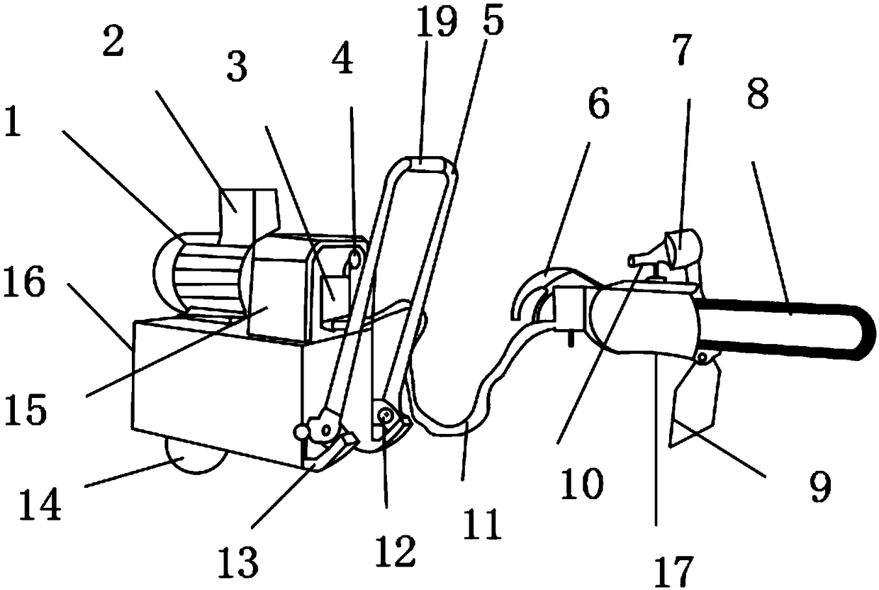
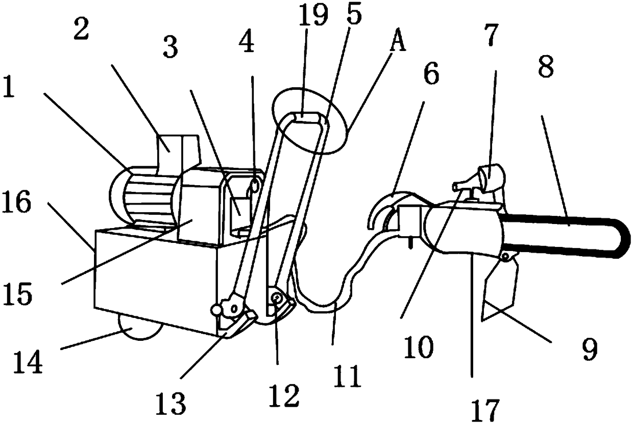
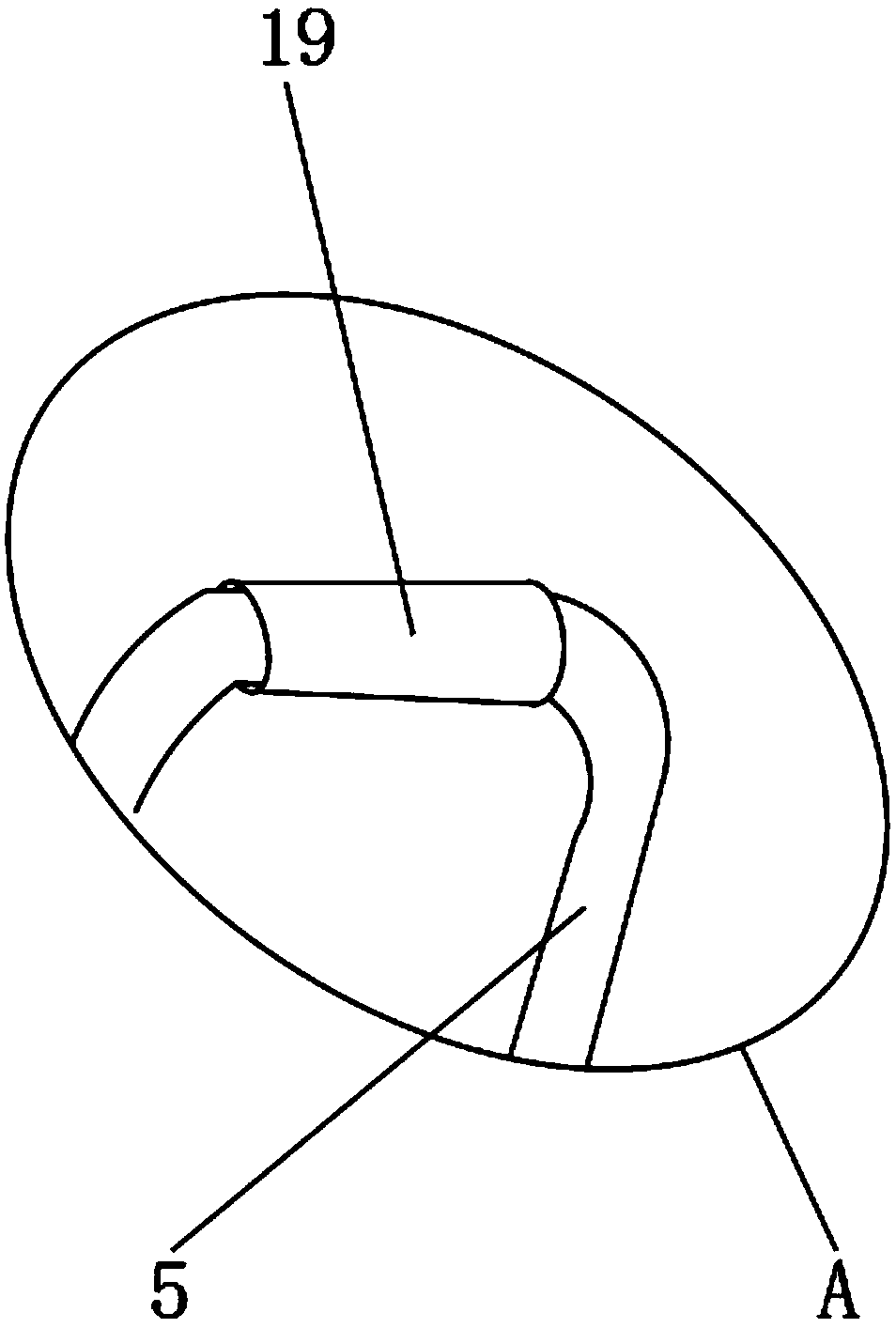
[0018] Such as Figure 1-4 As shown, a hydraulic saw that facilitates electric bed cutting includes a motor 1, an oil pipe 11, a bolt 12, and a hydraulic saw 17. A control box 2 is provided above the motor 1, and a protective plate 15 is provided on one side of the motor 1. , the bottom end of the motor 1 is provided with a fuel tank 16, and the bottom end of the fuel tank 16 is provided with a roller 14 and an anti-collision frame 13, and the upper end of the anti-collision frame 13 is provided with a rectangular pull rod 5, and the rectangular pull rod 5 passes through the bolt 12 It is movably connected with the anti-collision frame 13, and the inside of the protective plate 15 is provided with a hydraulic pump 3 and a cooling fan 18, and the u...


PUM


Abstract

The invention discloses a hydraulic saw for convenient electric bed cutting. The hydraulic saw comprises an electric motor, an oil pipe, bolts and a hydraulic saw body. A control box is arranged abovethe electric motor, and a protective plate is arranged on one side of the electric motor. A fuel tank is arranged at the bottom end of the electric motor, and a rectangular pull rod is arranged at the upper ends of anti-collision frames. The protective plate is internally provided with a hydraulic pump and a cooling fan, and a pressure indicator gauge is fixedly mounted at the upper end of the hydraulic pump. A portable switch and a portable handle are arranged on the outer surface of the hydraulic saw body. The hydraulic saw for convenient electric bed cutting is provided with an anti-slip rubber sleeve, the cooling fan and a saw blade speed regulating device, the friction between a worker and the rectangular pull rod can be increased, the heat during the working of the hydraulic saw isdischarged, the hydraulic saw is kept at a certain temperature, and the speed of a saw blade is adjusted; and the hydraulic saw is suitable for cutting various large objects, is suitable for differentworking conditions, and brings better use prospects.

Description

technical field [0001] The invention relates to the field of mechanical equipment, in particular to a hydraulic saw that is convenient for electric bed cutting. Background technique [0002] Chainsaw, also known as "power saw", was invented by German Andreas. Invented by Steele in 1926, it greatly saves the time and labor spent on cutting materials. A chainsaw is powered by electricity and is a cutting tool used to cut wood, stone, steel, etc., with sharp teeth on the edge. Separate fixed and portable, the saw blade is generally made of tool steel, there are round, strip and chain and so on. Hydraulic transmission has many outstanding advantages, so it is widely used, such as plastic processing machinery, pressure machinery, machine tools, etc. for general industrial use; construction machinery, construction machinery, agricultural machinery, automobiles, etc. in walking machinery; Metallurgical machinery, lifting devices, roll adjustment devices, etc.; flood control gate...

Claims


Application Information

Patent Timeline
Patent Type & Authority Applications(China)
IPC IPC(8): B23D49/16B23D51/00B23D51/18B23D59/00B23Q11/08B23Q11/12
CPCB23D49/16B23D51/00B23D51/18B23D59/00B23Q11/08B23Q11/126
Inventor 朱桂林
Owner JIAXING WEITELA ELECTRICAL SCI & TECH CO LTD
Why Eureka
Try Eureka