Eureka AIR delivers breakthrough ideas for toughest innovation challenges, trusted by R&D personnel around the world.

Resilient floor

a resilient material and floor technology, applied in the field of floorboard assembly, can solve the problems of difficult use, difficult to use, and difficult to use angling, and achieve the effect of reducing the force needed for connection of the floorboards and increasing the friction of the resilient material

Active Publication Date: 2013-02-05
VÄLINGE INNOVATION AB
View PDF193 Cites 153 Cited by
  • Summary
  • Abstract
  • Description
  • Claims
  • Application Information

AI Technical Summary

Benefits of technology

[0004]A method is disclosed for assembling of floorboards, which are so called resilient floorboards i.e. the core is of a resilient material for example vinyl or PVC. The known methods of assembling floorboards that are mentioned above are difficult to use when assembling resilient floorboards since resilient floorboards easily bend which make it hard to use the angling-angling method and it is unfeasible to use the angling-snapping method since it requires a force to be applied, at an opposite edge in relation to the edge of the floorboard which is intended to be connected, by e.g. a hammer and a tapping block and the resilient core of the resilient floorboard absorbs the applied force. The known vertical folding methods are also difficult to apply due to the increased friction in the resilient material. The disclosed method makes the assembling easier and reduces the force needed for connection of the floorboards.
[0005]Furthermore, a locking system suitable for the method is disclosed. The locking system decreases the friction forces that must be overcome when installing the resilient floorboards.
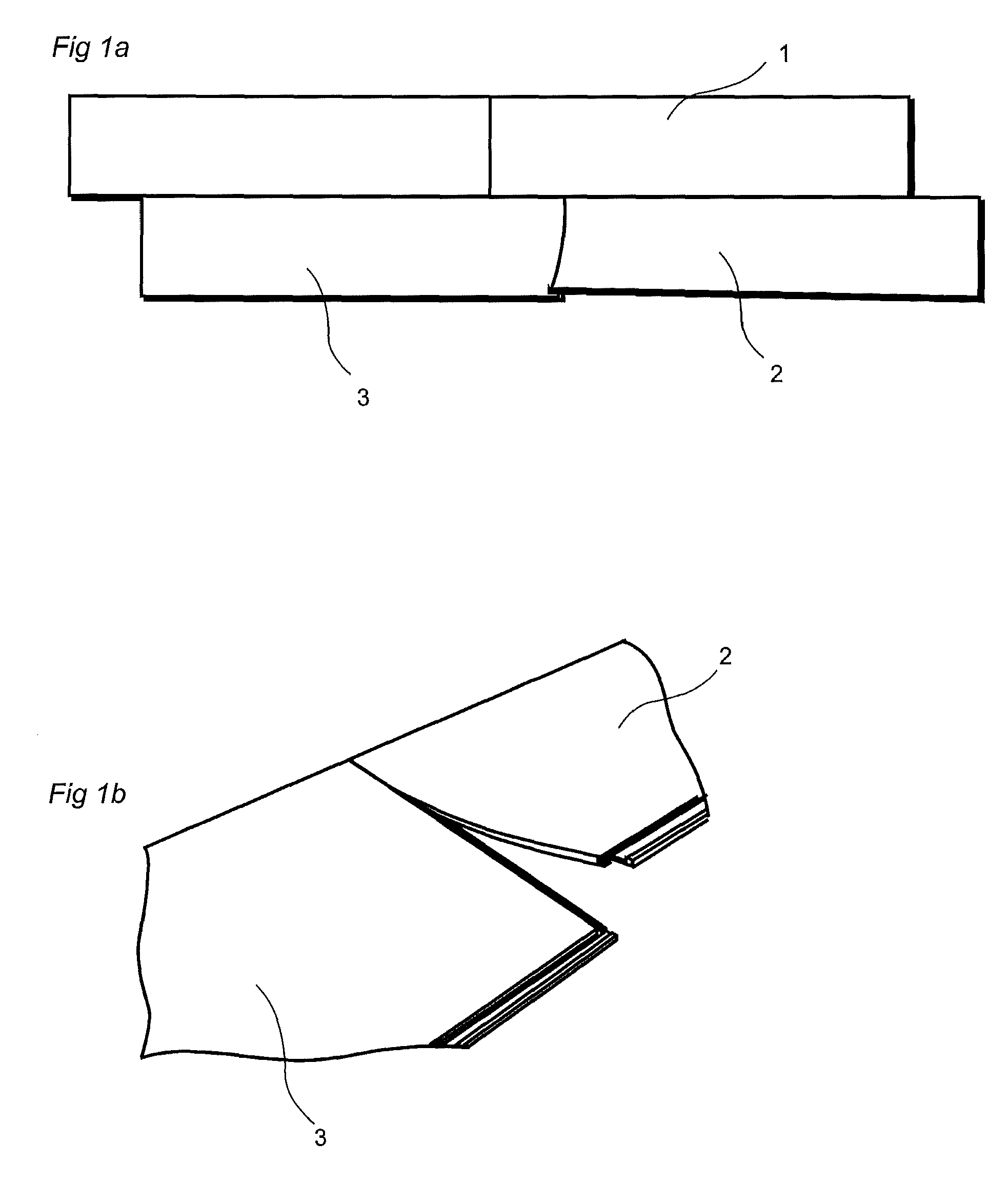
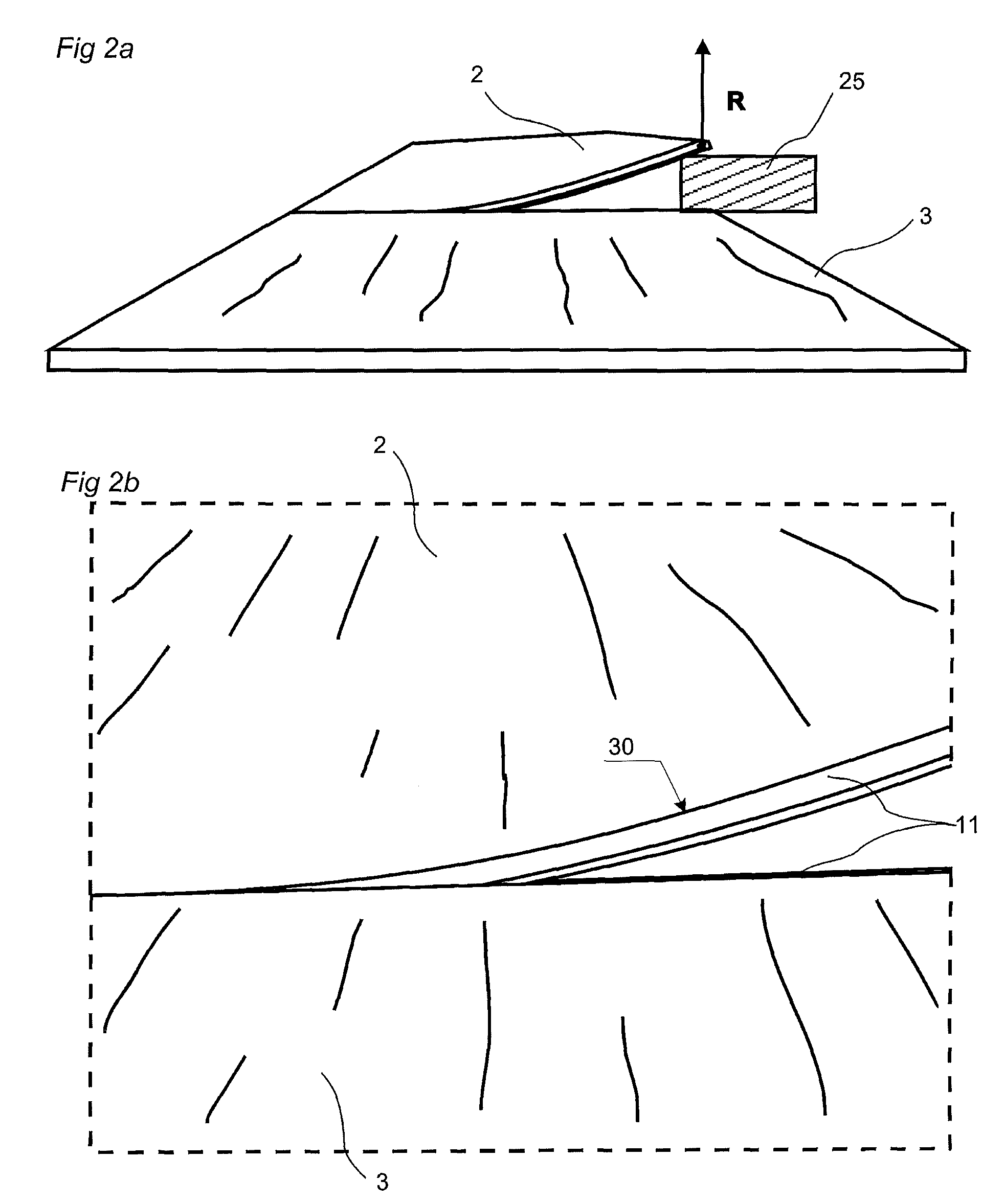
[0010]The bending makes it possible to finalize the connection of only a part of the edge of the floorboard, instead of the whole edge as in the known methods, and consequently the force needed to assemble the floorboards is considerably reduced.

Problems solved by technology

The known methods of assembling floorboards that are mentioned above are difficult to use when assembling resilient floorboards since resilient floorboards easily bend which make it hard to use the angling-angling method and it is unfeasible to use the angling-snapping method since it requires a force to be applied, at an opposite edge in relation to the edge of the floorboard which is intended to be connected, by e.g. a hammer and a tapping block and the resilient core of the resilient floorboard absorbs the applied force.
The known vertical folding methods are also difficult to apply due to the increased friction in the resilient material.

Method used


Image

  • Resilient floor
  • Resilient floor
  • Resilient floor

Examples


Embodiment Construction

[0027]An embodiment of a method of assembling resilient floorboards (1, 2, 3) with a mechanical locking system 11 is shown in FIGS. 1a and 1b. An edge of a floorboard 2 is positioned juxtaposed another edge of another floorboard 3. The edge of the floorboard is bent (30) along the edge during the assembling and the connection of the floorboard edges to each other. In this embodiment the edge and said another edge are short edges and a long edge of the floorboard is connected to a long edge of a floorboard 1 in another row, by a mechanical angling locking system, simultaneous with the short edge connection, by an angular motion.

[0028]An embodiment of a mechanical angling locking system is shown in FIGS. 5a and 5b. Embodiments of the mechanical locking system 11 at the short edges is shown in FIGS. 6a to 9a. When assembling a complete floor the method shown in FIG. 1a is naturally applied and repeated for each resilient floorboard, which is provided with the locking system at each sho...


PUM

PropertyMeasurementUnit
angleaaaaaaaaaa
angleaaaaaaaaaa
angleaaaaaaaaaa

Abstract

A method of assembling resilient floorboards is disclosed that includes the step of bending an edge of a floorboard during the assembling. The bending reduces the force required for connection of the edge to another edge of a juxtaposed floorboard.

Description

CROSS-REFERENCE TO RELATED APPLICATIONS[0001]This application claims benefit to Application No. 61 / 239,927, filed Sep. 4, 2009. Application No. 61 / 239,927 is hereby incorporated by reference in its entirety.TECHNICAL FIELD[0002]The present invention generally concerns a method of assembling of floorboards provided with a mechanical locking system.BACKGROUND OF THE INVENTION[0003]Floorboards with a wood based core that are provided with a mechanical locking system and methods of assembling such floorboards by angling-angling, angling-snapping or vertical folding are disclosed in e.g. WO 94 / 26999, WO 01 / 77461, WO 2006 / 043893 and WO 01 / 75247. Floorboards of resilient material, e.g. PVC, are known, commonly referred to as LVT (Luxury Vinyl Tiles) that are glued down to the subfloor or bonded at the edges to each other WO 2008 / 008824.SUMMARY OF THE INVENTION[0004]A method is disclosed for assembling of floorboards, which are so called resilient floorboards i.e. the core is of a resilient...

Claims


Application Information

Patent Timeline
Patent Type & Authority Patents(United States)
IPC IPC(8): E04C1/00
CPCE04F15/10E04F15/02038E04B5/00E04F2201/0138Y10T29/49623E04F2201/0153E04F2201/0146E04F15/105
Inventor NILSSON, MATSNYGREN, PER
Owner VÄLINGE INNOVATION AB
Why Eureka
Eureka Blog
Learn More