Hot-melting drill-rivet rivet and drill-rivet connection method
A hot-melt drilling and rivet technology, applied to rivets, connecting components, screws, etc., can solve problems such as difficult penetration and easy damage to the rivet head, and achieve the effects of reducing resistance, improving riveting quality, and improving efficiency
- Summary
- Abstract
- Description
- Claims
- Application Information
AI Technical Summary
Problems solved by technology
Method used
Image
Examples
Embodiment 1
[0065] In one embodiment, the structure of the rivets used in the drill riveting connection of the present invention is as follows: figure 1 As shown, it includes a core rod 1 and a nail cap 2, wherein the structure of the core rod 1 is as figure 2 As shown, the shape of the head 11 of the core rod 1 is a cone, which is used to turn the connected workpiece to reduce the resistance of piercing the workpiece; the cross section of the tail 12 of the core rod 1 is hexagonal, octagonal Polygonal or circular with anti-slip teeth, used to cooperate with the sleeve or jaw connected to the drive motor, and transmit torque to the rivet head (that is, the head of the mandrel) when drilling and riveting; the middle part of the mandrel is provided with The breakpoint ring groove 13, after the riveting is completed, the core rod 1 is broken at the breakpoint ring groove 13.
[0066] exist figure 1 It can be seen in the figure that the nail cap 2 includes a cap head 21 and a cap tube 22, ...
Embodiment 2
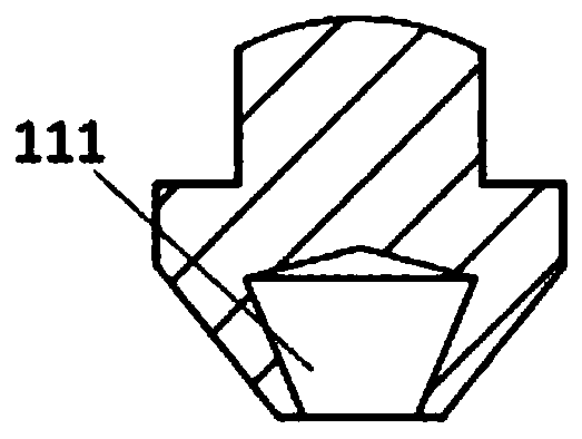
[0071] In this embodiment, the structure of the rivets used in the drill riveting connection of the present invention is as follows: Figure 9-11 as shown, Figure 9 is the front view of the rivet, Figure 10 sectional view for the front view of the rivet, Figure 11 Isometric view of a rivet. In this embodiment, the rivet includes a mandrel 1 and a nail cap 2, wherein a blind hole 111 is opened in the head 11 of the mandrel 1 in the axial direction, and the blind hole 111 can accommodate sheet material during penetration. , the outer peripheral wall of the head 22 is symmetrically provided with two cutouts 112, the cutouts 112 open upward from the bottom of the head 11, the cutouts 112 communicate with the blind hole 111, this arrangement makes all The head 11 fully accommodates the plate material as much as possible, and the two cuts 112 divide the lower end of the head 11 into two cutting point edges, which reduce the contact between the rivet and the connected workpiece...
Embodiment 3
[0077] In this embodiment, the rivet of this embodiment is a single-drum rivet structure, and its specific structure and riveting process are as follows: Figure 19-22 as shown, Figure 19 It is a schematic diagram of the state when the rivet rotates and reaches the workpiece 3 to be connected, Figure 20 It is a schematic diagram of the state where the rivet is stirring and cutting through the connected workpiece 3, Figure 21 It is a schematic diagram of the state of the single-drum locking structure produced by the cap tube 22 of the rivet being squeezed and deformed when the force in the opposite direction is applied to the mandrel 1 and the nut 2 of the rivet. Figure 22 It is a schematic diagram of the state where the core rod 1 is continuously pulled upwards and broken at the ring groove 13 at the breaking point. exist Figure 21 It can be seen from the figure that during the riveting process, the cap tube 22 of the nail cap is deformed to form a single-drum locking...
PUM
 Abstract
Description
Claims
Application Information
 - R&D
- Intellectual Property
- Life Sciences
- Materials
- Tech Scout
- Unparalleled Data Quality
- Higher Quality Content
- 60% Fewer Hallucinations
Browse by: Latest US Patents, China's latest patents, Technical Efficacy Thesaurus, Application Domain, Technology Topic, Popular Technical Reports.
© 2025 PatSnap. All rights reserved.Legal|Privacy policy|Modern Slavery Act Transparency Statement|Sitemap|About US| Contact US: help@patsnap.com


