Design method and device capable of eliminating hydraulic pulsation
A design method and hydraulic pulse technology, applied in the field of hydraulic pumps, can solve problems such as unstable speed, high cost, and adverse effects on the system, and achieve the effect of avoiding fluctuations in liquid flow and supplying liquid at a uniform speed
- Summary
- Abstract
- Description
- Claims
- Application Information
AI Technical Summary
Problems solved by technology
Method used
Image

Examples
Embodiment 1
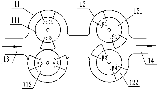
[0036] The method of the present invention can be applied to all types of gear pumps, including internal gear pumps and external gear pumps. In this embodiment, the external gear pump is taken as an example, such as figure 1 As shown, it is a structure for eliminating hydraulic pulses of a circumscribed gear pump, including gear pump A11 and gear pump B12 arranged in series, the gear pump A11 and gear pump B12 are arranged in the same cavity, one end of the cavity The gear pump A11 and the gear pump B12 are connected with the driving device, and are driven by the driving device to rotate at a constant angular speed. The gear pump A11 includes a rotary piston a 111 and a rotary piston b 112 that are matched with each other, the gear pump B12 includes a rotary piston c 121 and a rotary piston d 122, and each of the rotary piston a-rotary piston d is provided with a vane. The lobe is a fan-shaped lobe, the size and shape of the outer arc of the fan-shaped lobe on the rotary pisto...
Embodiment 2
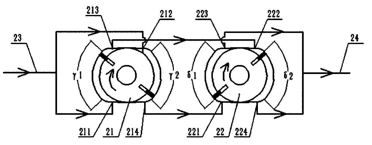
[0042] like figure 2 As shown, it is an embodiment designed for the vane pump using the method of the present invention. Taking two pump bodies connected in series as an example, the vane pump liquid supply system of this embodiment specifically includes a vane pump A21 and a vane pump B22. The vane pump Both A21 and vane pump B22 include a stator and a rotating rotor. The stator includes two arcs whose profiles are regular arcs, and the two arcs are located within the range of the pump oil angle. The liquid angles are γ1 and γ2, the pump liquid angle of the vane pump B22 is, the sum of the angles added by the γ1, γ2, δ1, and δ2 is at least 360°; and the transition curve connecting the perfect circular arcs at both ends is located at In the non-pump angle range, the transition curve is in tangential contact with the rotor. The rotor is connected with a driving device, and the driving device drives the rotor to rotate at a constant angular speed.
[0043] The following takes...
Embodiment 3
[0049] like Figure 5 As shown, a plunger pump is an embodiment when the technical solution of the present invention is applied, and this embodiment is described by taking two single plunger pumps connected in series as an example.
[0050] The plunger pump liquid supply system of this embodiment includes two single plunger pumps connected in series, plunger pump A31 and plunger pump B32. The plunger pump A31 includes a hydraulic cylinder a311 and a hydraulic cylinder b312. The hydraulic cylinder A311 and the piston rod of the hydraulic cylinder b312 are rigidly connected by the connecting piece a313, such as Image 6 As shown, the connecting piece a313 is a C-shaped piece, the two outer sides are respectively connected with the piston rods of the hydraulic cylinder a311 and the hydraulic cylinder b312, and the two inner sides of the connecting piece are in tangential contact with the cam a314, so that the The piston rod moves horizontally with the rotation of the cam. Since ...
PUM
 Abstract
Description
Claims
Application Information
 - R&D
- Intellectual Property
- Life Sciences
- Materials
- Tech Scout
- Unparalleled Data Quality
- Higher Quality Content
- 60% Fewer Hallucinations
Browse by: Latest US Patents, China's latest patents, Technical Efficacy Thesaurus, Application Domain, Technology Topic, Popular Technical Reports.
© 2025 PatSnap. All rights reserved.Legal|Privacy policy|Modern Slavery Act Transparency Statement|Sitemap|About US| Contact US: help@patsnap.com