
Adaptive control of an oil or gas well surface-mounted hydraulic pumping system and method

a hydraulic pumping system and adaptive control technology, applied in the direction of piston pumps, positive displacement liquid engines, borehole/well accessories, etc., can solve the problems of loss of production, uncontrolled impact loads between, and other factors that cannot be controlled, so as to reduce service and down time costs, enhance safety and durability, and optimize the productivity of oil and gas wells.

Active Publication Date: 2014-10-07
DYNAPUMP INC +1
View PDF18 Cites 112 Cited by
  • Summary
  • Abstract
  • Description
  • Claims
  • Application Information

AI Technical Summary

Benefits of technology

The invention introduces a new hydraulic surface pump and control system that can optimize its production capacity by varying multiple operating parameters, such as stroking length and speed characteristics, in real-time and closed loop. This increases power efficiency, durability, and longevity of the pumping equipment while reducing power consumption and adapting effectively to changing well conditions. The system and method improve oil and gas well performance with little or no need for operator intervention, especially in remote locations where operator intervention is challenging.

Problems solved by technology

Petroleum well characteristics undergo changes during the operating life of the well, some of which the well operator can manage directly while others can be hardly controlled.
Floating of the polished rod on the down stroke can cause separation of the polished rod from the carrier bar, leading to uncontrolled impact loads between them when they come back together on the up stroke.
Operation at speeds lower than the optimal speed causes loss of production.
Operation in pumped off conditions is causing pounding loads between the pumping equipment and the fluid, resulting in overstressing of structural parts, their premature damage, high maintenance costs and a shortened life of the pumping equipment.
The position, velocity and acceleration sinusoidal characteristics of the polished rod are very complicated and are, therefore, hard to control by the crank arm drive in real time.
The difficulty to control these parameters is greatly compounded by typical large dynamic inertias of the moving parts of the beam pump and its balancing weights.
Moreover, most present technologies do not enable to set different up and down speeds, as optimization of pumping performance often requires.
Most systems are not smart enough to “safe land” the system softly without causing major damage, costly maintenance and wasted production down time.
This does not disclose continuously monitoring the pump and also does not use a hydraulic piston but instead discloses use of a DC motor pump assembly.
In addition, the pump and the control system disclosed in the Thrasher patents are subjected to premature failure of the downhole pump due to lack of lubrication and overheating when operating in gassy wells.
They are also subjected to premature failure when operating in sandy wells due to surface erosion and damage by the abrasive sand contents in the fluid.

Method used


Image

  • Adaptive control of an oil or gas well surface-mounted hydraulic pumping system and method
  • Adaptive control of an oil or gas well surface-mounted hydraulic pumping system and method
  • Adaptive control of an oil or gas well surface-mounted hydraulic pumping system and method

Examples


Embodiment Construction

[0065]Although specific embodiments of the presented invention are described herein with reference to the drawings, it should be understood that such embodiments are by way of example only. They merely illustrate but a small number of the many specific embodiments which can represent applications of the principles of the present invention. Various changes and modifications, obvious to one skilled in the art to which the present invention pertains, are deemed to be within the spirit, scope and contemplation of the present invention as further defined in the appended claims.

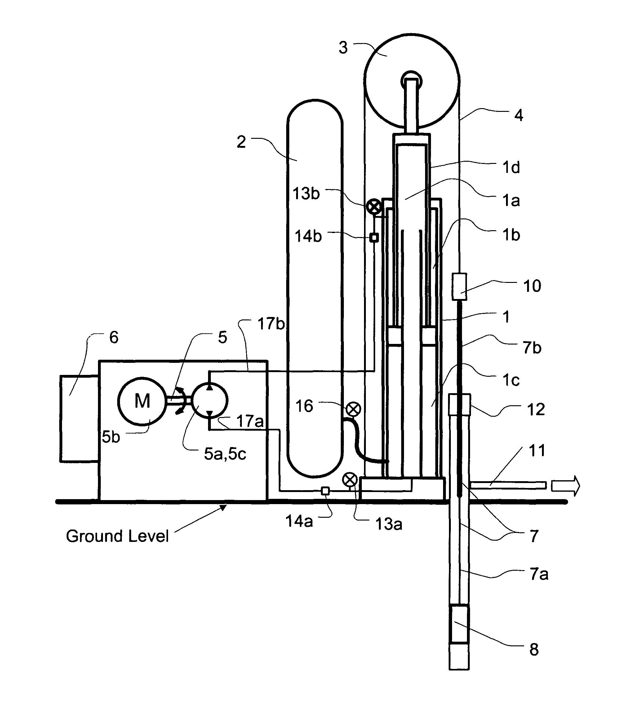
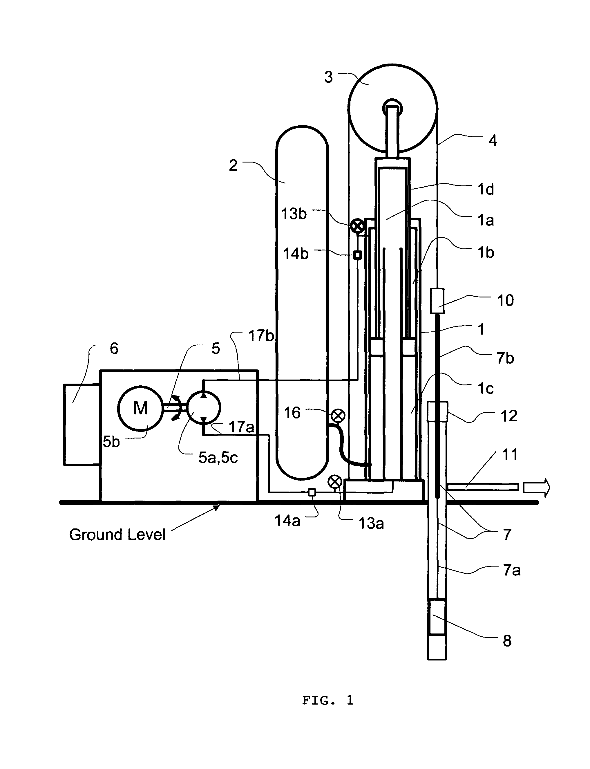
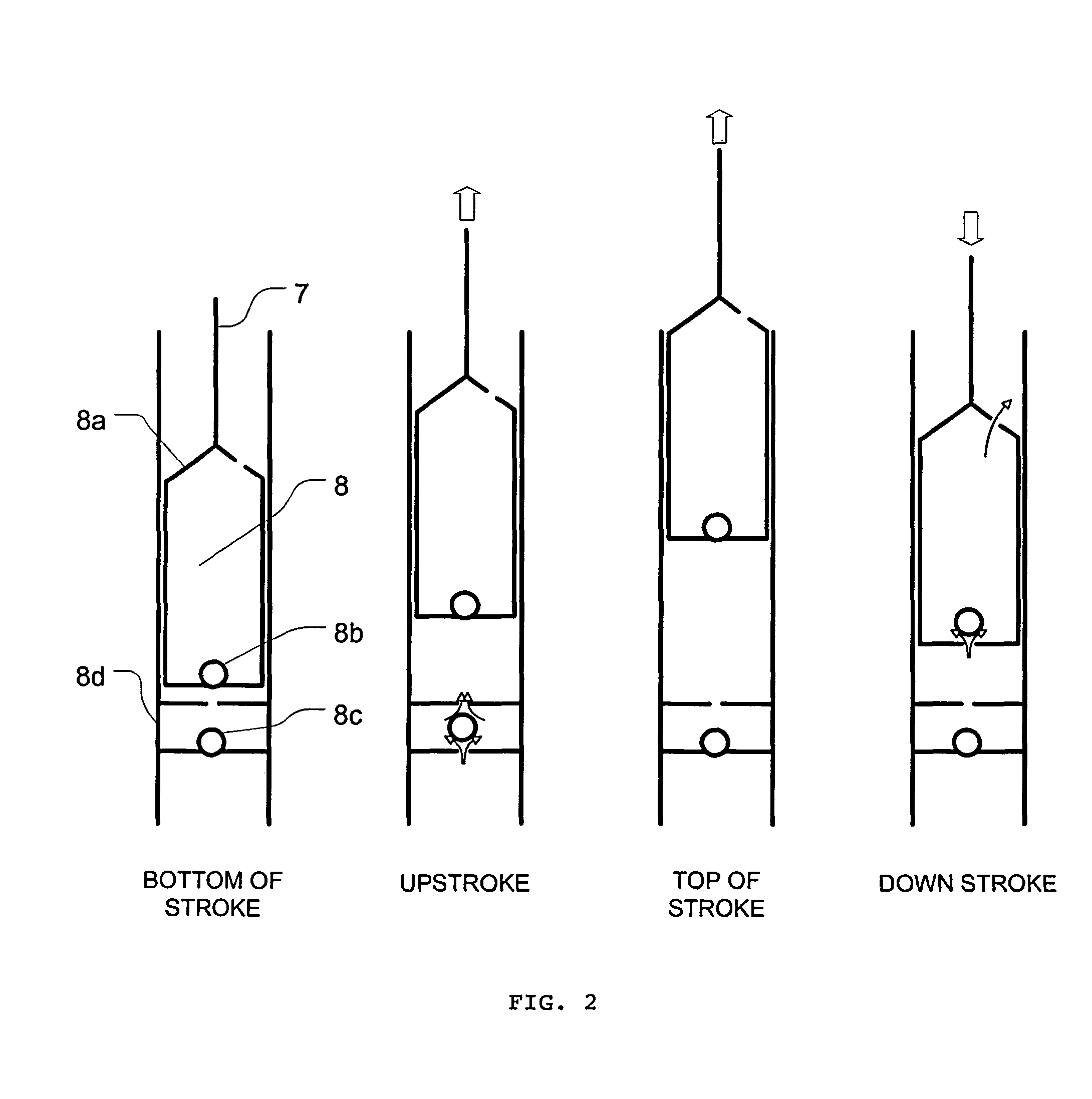
[0066]The disclosed invention features an intelligent adaptive control system and method, used in conjunction with a long stroke hydraulic lift system, applied at the surface of an oil well, or a gas well, to pump fluid or gas. When used with an oil well the system is used to extract a mixture of oil, gas and water. When used with a gas well the system is used to remove water from the well (dewatering) to free up f...


PUM


Abstract

The disclosed invention provides intelligent adaptive control for optimization of production output, energy efficiency and safety of a linear reciprocating long stroke hydraulic lift system, for use at the surface of oil and gas wells to extract fluids or gas after free flowing stopped due to natural decline of reservoir pressure.The hydraulic pump and its adaptive control system introduced in this invention are capable of optimizing its production capacity by varying multiple operating parameters, including its stroking length and speed characteristics continuously and instantaneously at any point. Merits and benefits of this invention include significant increase in production efficiency, improved durability and longevity of the pumping equipment, significant power consumption savings and an ability to adapt effectively to changing well conditions.

Description

[0001]This patent application claims priority to Application No. 61 / 210,926 filed on Mar. 23, 2009.BACKGROUND OF THE INVENTION[0002]1. Field of the Invention[0003]This invention relates to artificial lift of fluids and gas from subsurface reservoirs. More specifically it relates to performance optimization of fluid and gas artificial recovery from subsurface formations, using a surface mounted reciprocating hydraulic pump, controlled by a computer and a set of specific algorithms.[0004]2. Description of Prior Art[0005]Flow into a petroleum well bore depends upon the characteristics of the reservoir formation and its fluids. It also depends upon the well bore conditions while it is producing. Petroleum well characteristics undergo changes during the operating life of the well, some of which the well operator can manage directly while others can be hardly controlled. After an initial phase of free flowing production and as reservoir pressure is declining, there is a need to employ art...

Claims


Application Information

Patent Timeline
IPC IPC(8): F04B49/00
CPCF04B2205/11F04B49/065F04B49/00F04B47/02
Inventor MAIL, JACOB
Owner DYNAPUMP INC
Learn More