CAN (Controller Area Network) analysis circuit and method for new energy vehicles
A technology of new energy vehicles and circuits, which is applied in the field of CAN analysis circuits of new energy vehicles, can solve the problems of signal safety and reliability, insufficient fault tolerance, interference signals and static interference, etc., and achieve the suppression of electromagnetic waves from radiating outward , Improve the anti-interference ability, improve the effect of transmission quality
- Summary
- Abstract
- Description
- Claims
- Application Information
AI Technical Summary
Problems solved by technology
Method used
Image
Examples
Embodiment 1
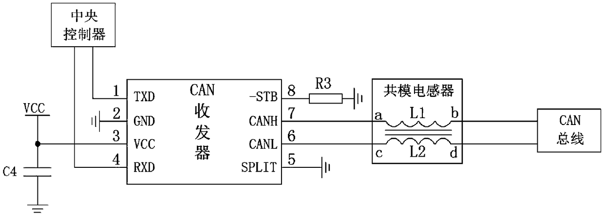
[0039] See figure 1 As shown, a CAN analysis circuit for a new energy vehicle includes a CAN transceiver and a common mode inductor; the CAN transceiver is provided with a transmitting terminal 1 for sending CAN parameter signals to a central controller and a receiving center The receiving terminal 4 of the control signal sent by the processor is also provided with a high voltage terminal 7 and a low voltage terminal 6; the common mode inductor includes a first inductor L1 and a second inductor L2 arranged in common mode induction; The first end a of the first inductor L1 is connected to the high voltage end 7, and the second end b of the first inductor L1 is used to connect to the high voltage signal line of the CAN bus; the second end of the second inductor L2 One end c is connected to the low voltage end 6, and the second end d of the second inductor L2 is used to connect to the low voltage signal line of the CAN bus.
[0040] The CAN analysis circuit for new energy vehicles i...
Embodiment 2
[0041] Embodiment 2. This embodiment is improved on the basis of Embodiment 1. The content described in Embodiment 1 is also included in this embodiment, and will not be detailed here.
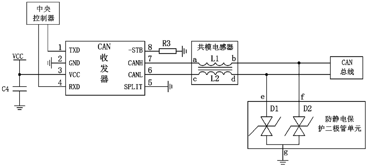
[0042] See figure 2 As shown, the CAN analysis circuit for new energy vehicles further includes an anti-static protection diode unit, and the first end e of the anti-static protection diode unit is connected to the second end d of the second inductor L2, so The second terminal f of the anti-static protection diode unit is connected to the second terminal b of the first inductor L1, and the third terminal g of the anti-static protection diode unit is grounded. The anti-static protection diode unit includes a first anti-static protection diode D1 and a second anti-static protection diode D2. One end of the first anti-static protection diode D1 is connected to the second end d of the second inductor L2, so The other end of the first antistatic protection diode D1 is grounded; one end of the second ...
Embodiment 3
[0044] The third embodiment, this embodiment is improved on the basis of the first embodiment, and the content described in the first embodiment also has this embodiment, and will not be described in detail here.
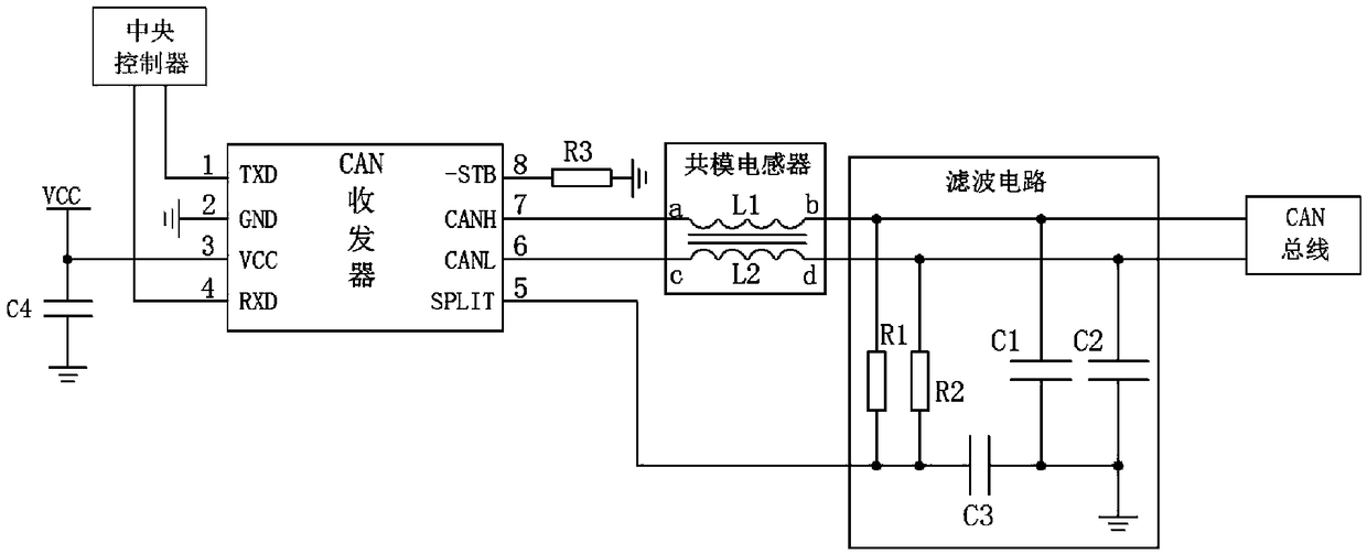
[0045] See image 3 As shown, the CAN analysis circuit for new energy vehicles further includes a filter circuit, one end of the filter circuit is respectively connected to the second end b of the first inductor L1 and the second end of the second inductor L2 d connection, the other end of the filter circuit is connected to the reference signal terminal 5 of the CAN transceiver. The filter circuit includes a first resistor R1, a first capacitor C1, and a third capacitor C3; the first capacitor plate of the third capacitor C3 is connected to the reference signal terminal 5 of the CAN transceiver, and the third capacitor C3 The second capacitor plate of the first resistor R1 is connected to the ground; both ends of the first resistor R1 are respectively connected to the ...
PUM
 Abstract
Description
Claims
Application Information
 - R&D
- Intellectual Property
- Life Sciences
- Materials
- Tech Scout
- Unparalleled Data Quality
- Higher Quality Content
- 60% Fewer Hallucinations
Browse by: Latest US Patents, China's latest patents, Technical Efficacy Thesaurus, Application Domain, Technology Topic, Popular Technical Reports.
© 2025 PatSnap. All rights reserved.Legal|Privacy policy|Modern Slavery Act Transparency Statement|Sitemap|About US| Contact US: help@patsnap.com


