
Full-optical-fiber electro-optical modulation system

An electro-optic modulation, all-fiber technology, used in optics, nonlinear optics, instruments, etc., can solve problems such as serious insertion loss, and achieve the effects of superior performance, strong controllability, and low cost.

Inactive Publication Date: 2018-11-06
SHANGHAI UNIV
View PDF5 Cites 1 Cited by
  • Summary
  • Abstract
  • Description
  • Claims
  • Application Information

AI Technical Summary

Problems solved by technology

In this process, due to the transmission across the medium, there is a relatively serious insertion loss
At the same time, since lithium niobate is solid at room temperature, further processing is required in application environments that require specific shapes, which increases the cost of equipment

Method used


Image

  • Full-optical-fiber electro-optical modulation system
  • Full-optical-fiber electro-optical modulation system
  • Full-optical-fiber electro-optical modulation system

Examples


Embodiment Construction

[0018] The present invention will be described in detail below in conjunction with the accompanying drawings and specific embodiments.

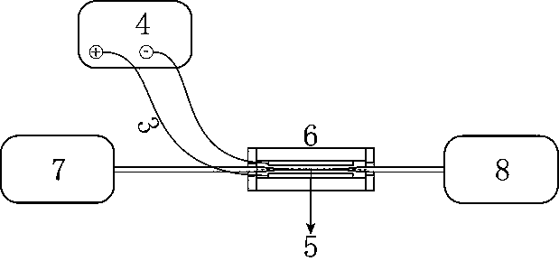
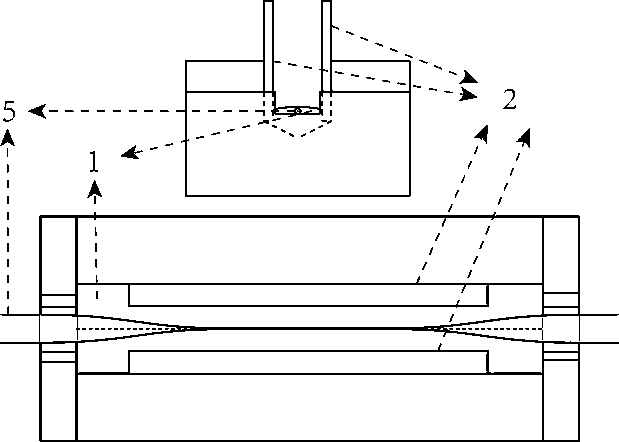
[0019] see figure 1 , an all-fiber electro-optic modulation system, comprising an ionic liquid 1, a platinum electrode 2, a wire 3, a DC power supply 4, a biconical optical fiber 5, and a U-shaped groove 6, and the platinum electrode 2 is placed vertically in the U-shaped groove 6 on both sides of the inner wall, and connected with the DC stabilized power supply 4 by the wire 3; place the cone part of the double-tapered optical fiber 5 between the two platinum electrodes 4 in the U-shaped groove 6; Ionic liquid 1.

[0020] A light source 7 is provided at the front end of the biconical optical fiber 5, and a spectrometer 8 is provided at the rear end of the biconical optical fiber 5. When the optical signal passes through the biconical optical fiber 5, a part of the optical signal will be transmitted along the surface of the biconical optical...


PUM


Abstract

The invention relates to a full-optical-fiber electro-optical modulation system. The full-optical-fiber electro-optical modulation system comprises an ionic liquid, platinum electrodes, wires, a DC stabilized power supply, a double tapered optical fiber and a U-shaped groove, wherein the platinum electrodes are vertically placed at the two sides of the inner wall of the U-shaped groove and are connected with the DC stabilized power supply through the wires; a double tapered optical fiber tapered area is partially placed between the two platinum electrodes in the U-shaped groove; and the U-shaped groove internally contains the ionic liquid. The distributing states of negative ions and positive ions in the ionic liquid can have a certain change along with the strength and direction of an external electric field, thereby changing the transmission characteristic of the ionic liquid; and the spectrum shape of an evanescent wave transmitted on the surface of the tapered optical fiber can change under the effect of the environmental factor, so that the spectrum shape of an optical signal transmitted by the tapered optical fiber changes. According to the full-optical-fiber electro-opticalmodulation system, the external electric field is controlled by changing the strength and direction of voltage applied to the platinum electrodes in the system, and the modulation characteristic of optical switch, electro-optical modulation and the like can be obtained.

Description

technical field [0001] The invention relates to the fields of optical fiber communication and optical fiber sensing, in particular to an all-fiber electro-optic modulation system. Background technique [0002] In high-speed long-distance communication, external modulation is the most important modulation method. Commonly used external modulators include: electro-optic crystal modulators, polarized polymer optical modulators, and semiconductor optical modulators. The main principle of the modulator is the direct electro-optic effect. Organic polymer electro-optic materials have many advantages, such as: low relative permittivity, easier to achieve high-frequency characteristics; wide variety of choices; high electro-optic coefficient. These advantages make polymer electro-optic materials the best choice for electro-optic modulators, but due to their poor stability and high loss, they have not been widely used yet. Polarized polymer light modulators are called next-generatio...

Claims


Application Information

Patent Timeline
IPC IPC(8): G02F1/00G02F1/01
CPCG02F1/0018G02F1/011
Inventor 陈振宜蒋志红王廷云陈娜庞拂飞刘书朋
Owner SHANGHAI UNIV
Learn More