
Steel back gluing device for brake clutch plate production

A technology of gluing device and clutch plate, which is applied to devices and coatings that apply liquid to the surface, can solve problems such as affecting the processing of steel backs, waste of glue, uneven gluing, etc., so as to improve production efficiency and save glue. material, the effect of accurate gluing

Inactive Publication Date: 2018-11-06
ANHUI GUIDA AUTO PARTS
View PDF6 Cites 1 Cited by
  • Summary
  • Abstract
  • Description
  • Claims
  • Application Information

AI Technical Summary

Problems solved by technology

[0003] Existing steel backs come in various styles, among which, in order to enhance the bonding strength with the friction plate, a steel back is provided with several connecting through holes on the steel back, and the steel back needs to be glued during the production process of the brake pads. However, when the existing gluing device applies glue to this steel back with connection holes, there is uneven glue application, and glue is also coated in the connection holes that do not need to be glued on the steel back, which affects the quality of the steel back. The next step of processing also causes a waste of glue. Therefore, it is urgent to develop a steel-backed gluing device for the production of brake clutch discs that is evenly glued, accurately positioned, saves glue consumption, is simple to operate, and is convenient to use.

Method used


Image

  • Steel back gluing device for brake clutch plate production
  • Steel back gluing device for brake clutch plate production
  • Steel back gluing device for brake clutch plate production

Examples


Embodiment Construction

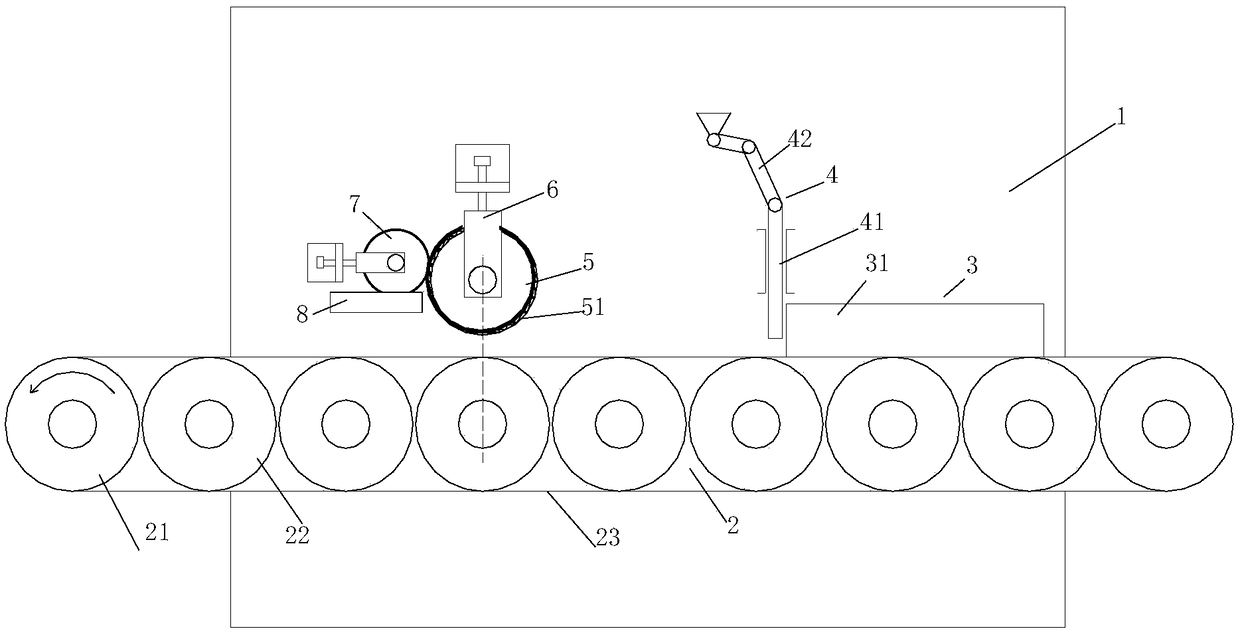
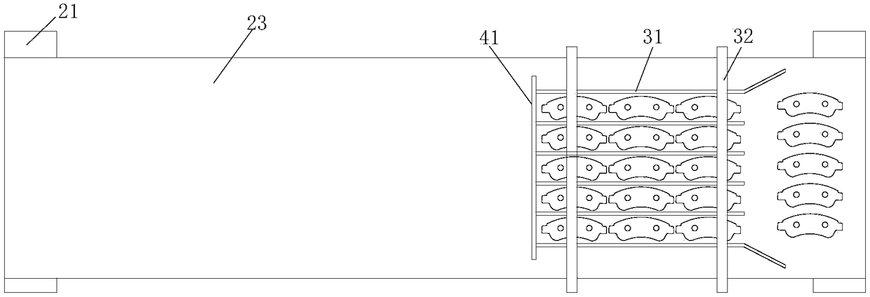
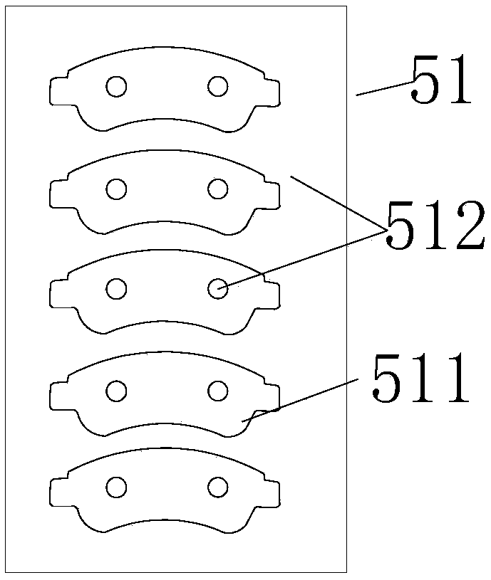
[0018] Such as Figure 1-3 as shown, figure 1 It is a structural schematic diagram of a steel back gluing device for the production of brake clutch discs proposed by the present invention; figure 2 It is a top view of part of the structure of a steel back glue coating device for the production of brake clutch discs proposed by the present invention; image 3 It is a schematic diagram of the development of the first roller of silica gel in a steel-back glue coating device for brake clutch plate production proposed by the present invention.

[0019] refer to Figure 1-3 , a steel back gluing device for the production of brake clutch discs proposed by the present invention has a connecting through hole on the steel back, and the upper surface of the steel back outside the connecting through hole is a gluing plane, including: frame 1, transmission mechanism 2, Guide plate mechanism 3, gluing mechanism.

[0020] Transmission mechanism 2 comprises conveyor belt 23, driving whee...


PUM


Abstract

The invention discloses a steel back gluing device for brake clutch plate production. The steel back gluing device comprises a rack, a transfer mechanism, a guide plate mechanism, a first rubber roller, a second rubber roller and a glue storage hopper, wherein the guide plate mechanism can be used for clearing up steel backs which are arranged disorderly on a conveyor belt, so that the steel backsare linearly and regularly arranged; a printing area and a non-printing area are arranged on first roller silica gel on the first rubber roller; after the first roller silica gel plane is expanded, the shape of the printing area is matched with glued surfaces of the steel backs; when the printing area glues the steel backs, only the printing area of the first rubber roller is in contact with theupper surfaces of the steel backs, and connecting through holes which do not need to glue in the steel backs are not in contact with the printing area on the first roller silica gel, so that product scrap due to the fact that the connecting through holes which do not need to glue in the steel backs are stained with glue can be prevented, and glue also can be saved. Therefore, the invention provides the steel back gluing device for the brake clutch plate production, and the steel back gluing device is uniform in gluing, is accurate in gluing position, saves glue usage amount and is convenient to use.

Description

technical field [0001] The invention relates to the technical field of production of brake clutch discs, in particular to a steel-back gluing device for production of brake clutch discs. Background technique [0002] Brake pads are generally composed of steel plates, adhesive insulation layers and friction blocks. The steel plates must be coated to prevent rust. During the coating process, a furnace temperature tracker is used to detect the temperature distribution during the coating process to ensure quality. The heat insulation layer is composed of materials that do not conduct heat, and the purpose is heat insulation. The friction block is composed of friction material and adhesive, which is squeezed on the brake disc or brake drum to generate friction during braking, so as to achieve the purpose of vehicle deceleration and braking. Due to friction, the friction block will be gradually worn, generally speaking, the lower the cost of the brake pads, the faster the wear. ...

Claims


Application Information

Patent Timeline
Patent Type & Authority Applications(China)
IPC IPC(8): B05C1/08B05C13/02
CPCB05C1/08B05C1/0834B05C13/02
Inventor 林和平
Owner ANHUI GUIDA AUTO PARTS
Learn More