Waste circulation type wood thermal cutting device

A circulating, thermal cutting technology, applied in grinding/polishing safety devices, grinding machines, charcoal burning/combustion, etc., can solve problems such as waste of resources

Pending Publication Date: 2018-10-12
重庆力迅家居有限公司
View PDF0 Cites 2 Cited by
  • Summary
  • Abstract
  • Description
  • Claims
  • Application Information

AI Technical Summary

Problems solved by technology

Discarding the polished charcoa

Method used


Image

  • Waste circulation type wood thermal cutting device
  • Waste circulation type wood thermal cutting device
  • Waste circulation type wood thermal cutting device

Examples


Embodiment Construction

[0020] The following is further described in detail through specific implementation methods:

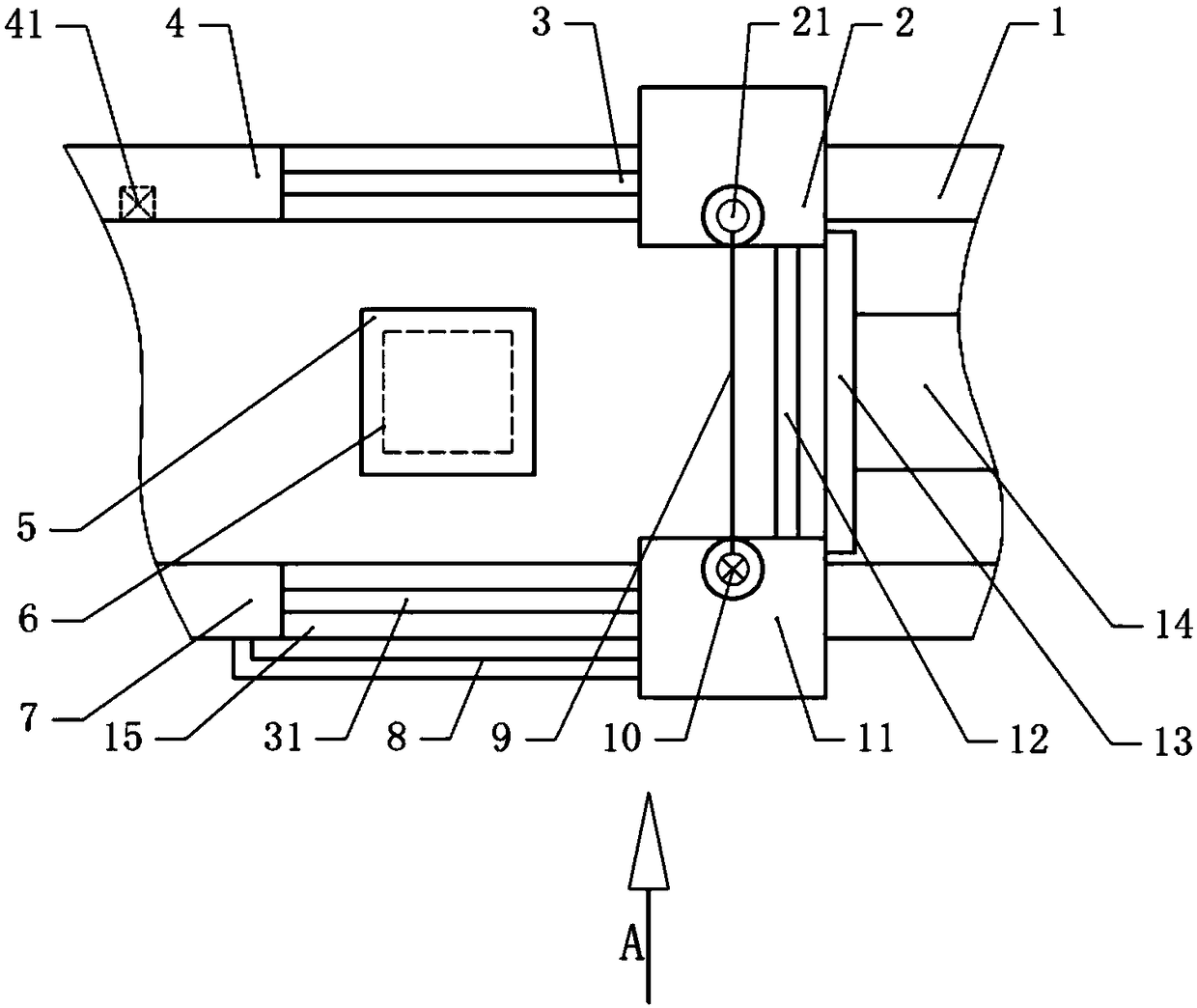
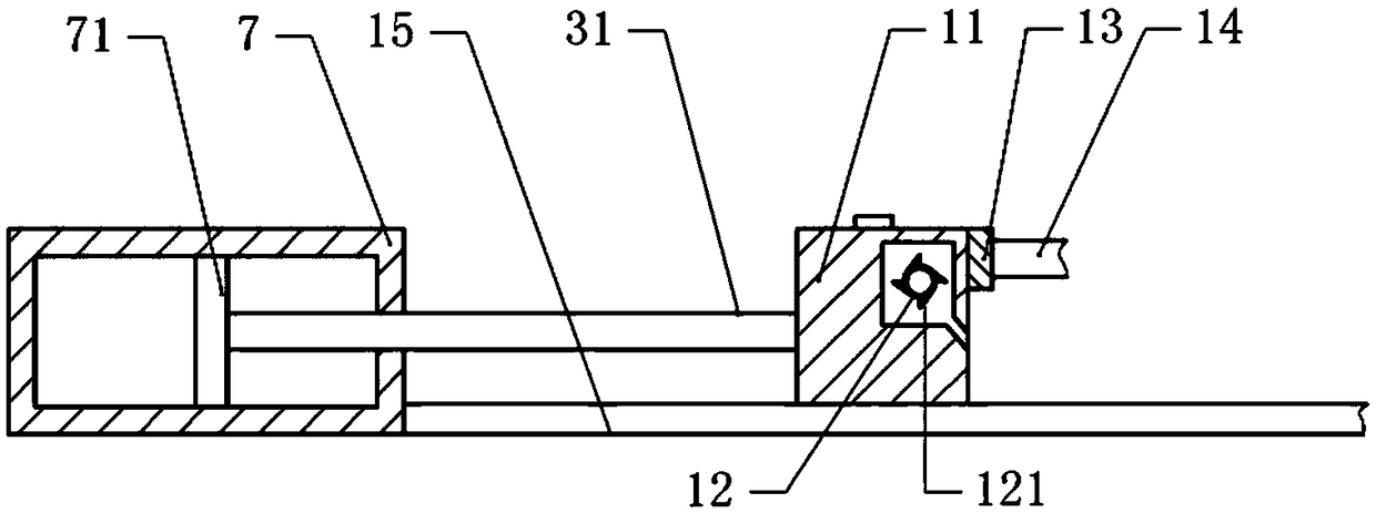
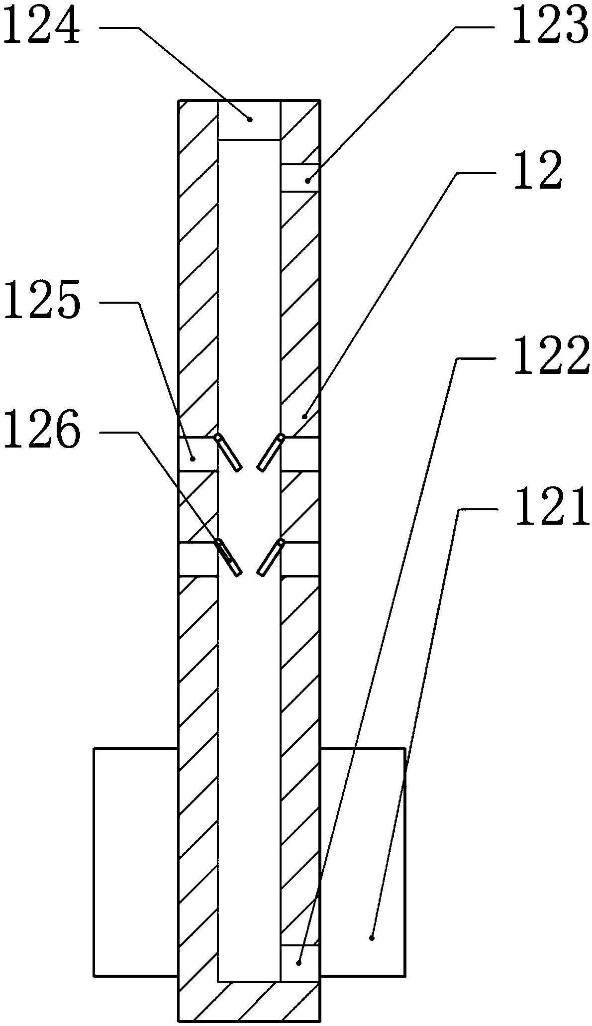
[0021] The reference signs in the drawings of the description include: the first slideway 1, the first slider 2, the connecting button 21, the first piston rod 3, the second piston rod 31, the first air box 4, the solenoid valve 41, the pressure plate 5 , wood 6, second air box 7, second piston plate 71, air pipe 8, alloy wire 9, heating device 10, second slider 11, polishing rod 12, fan blade 121, second outlet 122, first outlet 123 , inlet 124, opening 125, closing plate 126, connecting plate 13, output shaft 14, second slideway 15.

[0022] Waste recycling thermal wood cutting device, basically as attached figure 1 , comprising a frame and a first slideway 1 and a second slideway 15 arranged horizontally on the frame.

[0023] The right end of the first slideway 1 is horizontally slidably connected with the first slide block 2, and the left end of the first slideway 1 is fixed w...


PUM


Abstract

The invention relates to the technical field of wood door processing, and discloses a waste circulation type wood thermal cutting device. The waste circulation type wood thermal cutting device comprises a rack, a first sliding way and a second sliding way, wherein the first sliding way and the second sliding way are arranged on the rack and are horizontal. A first sliding block is in sliding connection to the first sliding way, a second sliding block is in sliding connection to the second sliding way, a connecting button is fixed to the first sliding block, and a heating device is fixed to thesecond sliding block and is electrically connected with an alloy wire fixedly connected with the connecting button. A second air box is fixed to the end, away from the second sliding block, of the second sliding way, a second piston plate is in sliding connection in the second air box, and a second piston rod is arranged between the second piston plate and the second sliding block. A containing table and a press plate are fixed to the rack. A grinding rod is arranged between the first sliding block and the second sliding block, multiple openings are formed in the side wall of the grinding rod, the second sliding block is provided with an air cavity communicating with the second air box, and one end of the grinding rod is located in the air cavity and fixedly provided with fan blades. Thewaste circulation type wood thermal cutting device is simple in structure, and a carbon layer formed by thermal cutting can be ground and recycled.

Description

technical field [0001] The invention relates to the technical field of wooden door processing, in particular to a waste recycling wood heat cutting device. Background technique [0002] In the wood cutting process, saws (saw blades, circular saws, band saws) are usually used to cut wood. When sawing is used to cut wood, the kerf is large, which wastes wood, especially for timber with a large diameter, the width of the kerf is greater than 8mm. Simultaneously, saw is easily deformed when cutting, and can not guarantee to walk straight line in cutting process, causes the thickness degree of the plank two ends of cutting to be inconsistent, brings inconvenience to use. [0003] In order to reduce the width of the incision and ensure a straight line during the cutting process, thermal cutting is used to cut the wood board. Existing thermal cutting burns the cut sawdust and forms a char layer. Therefore, it is also necessary to polish the kerf, which will inevitably reduce the...

Claims


Application Information

Patent Timeline
IPC IPC(8): B27M1/06B24B9/18B24B55/12
CPCB27M1/06B24B9/18B24B55/12
Inventor 赵红军
Owner 重庆力迅家居有限公司
Why Eureka
Try Eureka