
Forming method of 3D curved glass, forming system and 3D curved glass

A technology of curved glass and molding method, which is applied in glass molding, glass remolding, glass manufacturing equipment, etc., can solve the problems of low yield rate of mobile phone front cover, harm, long glass polishing time and no mass production.

Inactive Publication Date: 2018-09-28
深圳市太平洋自动化设备有限公司
View PDF2 Cites 6 Cited by
  • Summary
  • Abstract
  • Description
  • Claims
  • Application Information

AI Technical Summary

Problems solved by technology

[0003] The current 3D molding technology is divided into three types: the first is to use CNC equipment to clamp an electric spindle with a diamond grinding wheel rod rotating at high speed for cold grinding. This will cause two problems. Products with an arc height > 2mm cannot be done. Subsequent glass polishing time is too long and not suitable for mass production
The second is high-frequency non-contact induction heating, which will cause the mold to heat up and cool down quickly, resulting in residual stress in the glass and insufficient surface flatness. Only ordinary glass protection sheets with a thickness of about 0.33mm and high-alumina glass covers with a thickness of more than 0.5mm can be formed. The board cannot be produced, and high-frequency equipment will cause radiation to the human body, which is extremely harmful
The third type of molding equipment is a precision machine, but there are too few cooling stations for glass preheating and return, the control system is simple, all operations are manual, and the degree of automation is not high. There is no problem with the back cover of the mobile phone that is not very high, but the yield rate of the front cover of the mobile phone is too low
[0004] At present, the third type of precision molding equipment has defects such as incapable of automatic control of the whole process, inaccurate temperature control, high defect rate and long molding time.

Method used


Image

  • Forming method of 3D curved glass, forming system and 3D curved glass
  • Forming method of 3D curved glass, forming system and 3D curved glass
  • Forming method of 3D curved glass, forming system and 3D curved glass

Examples


Embodiment Construction

[0057] Specific embodiments of the present invention will be described in more detail below with reference to the accompanying drawings. Although specific embodiments of the invention are shown in the drawings, it should be understood that the invention may be embodied in various forms and is not limited to the embodiments set forth herein. Rather, these embodiments are provided for more thorough understanding of the present invention and to fully convey the scope of the present invention to those skilled in the art.

[0058] It should be noted that certain terms are used in the specification and claims to refer to specific components. Those skilled in the art should understand that they may use different terms to refer to the same component. The specification and claims do not use differences in nouns as a way of distinguishing components, but use differences in functions of components as a criterion for distinguishing. "Includes" or "comprises" mentioned throughout the spe...


PUM


Abstract

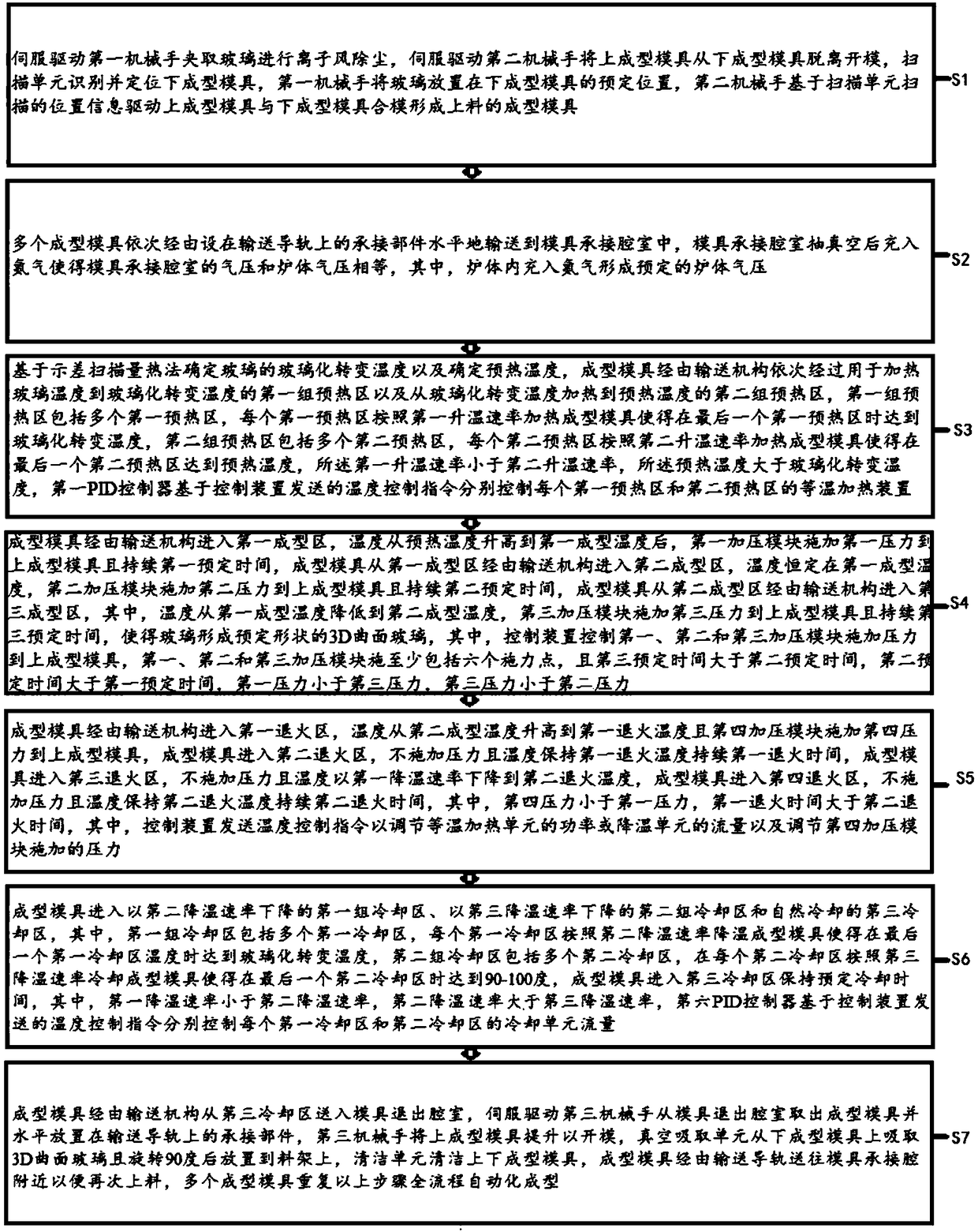
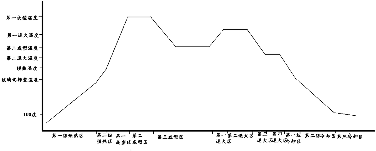
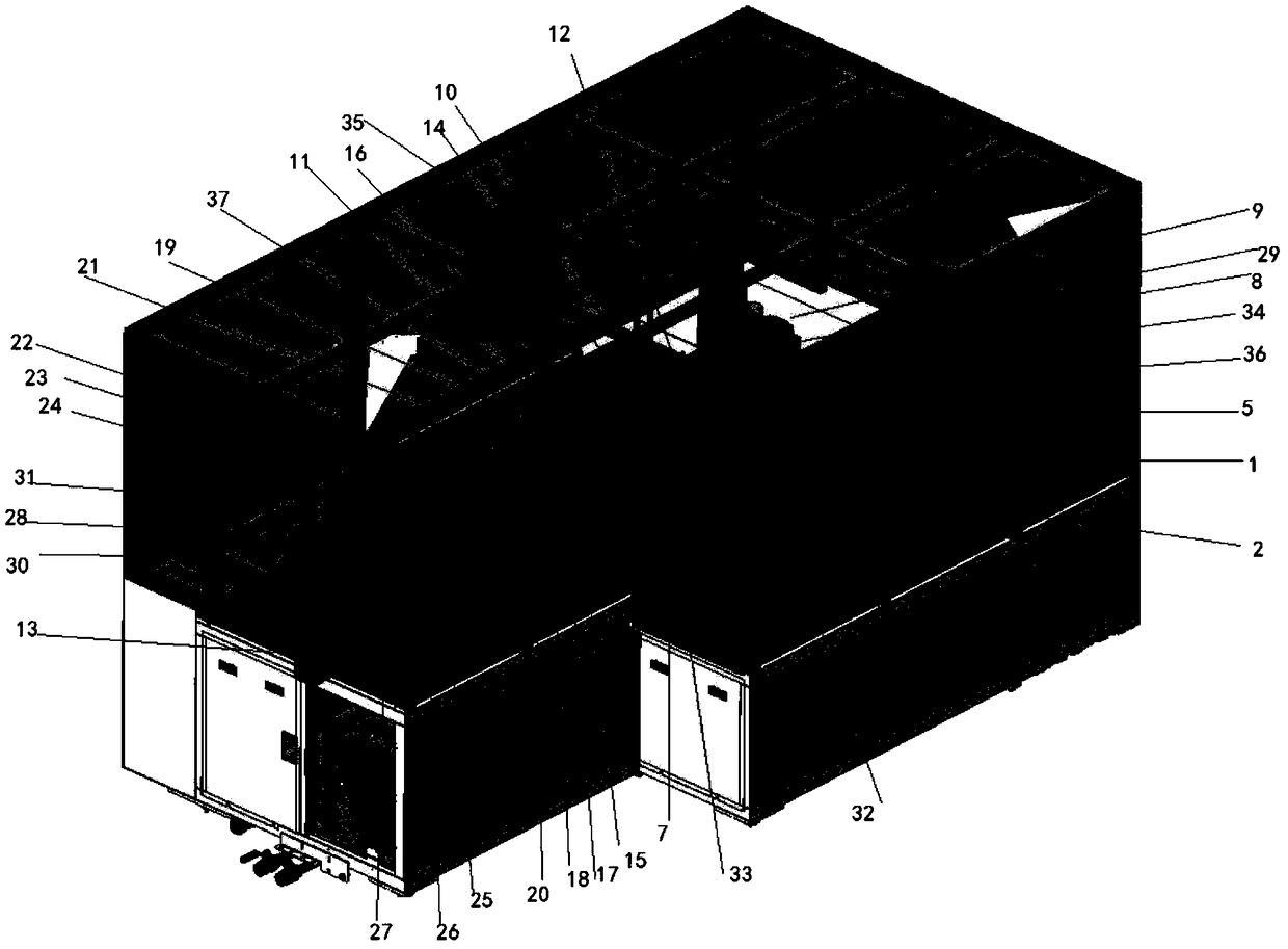
The invention discloses a forming method of 3D curved glass, a forming system and the 3D curved glass. The forming method of the 3D curved glass comprises the following steps: a second manipulator (2)performs die assembling on the basis of position information scanned by a scanning unit (5) to form forming dies (6) for loading materials; the multiple forming dies (6) are horizontally conveyed into a die carrying cavity (8) in sequence; after being vacuumized, the die carrying cavity (8) is filled with nitrogen to enable gas pressure in the die carrying cavity (8) to be equal to that of a furnace body (9); the forming dies (6) pass through a first group of preheating regions (10) for heating glass from a temperature to a glass transition temperature and a second group of preheating regions(11) for heating the glass from the glass transition temperature to a preheating temperature in sequence through a conveying mechanism; after being formed, annealed and cooled, the forming dies (6) are conveyed to a position near to the die carrying die (8) through a conveying guide rail (7) for material reloading; the multiple forming dies (6) are repeatedly subjected to the processes to realizeautomatic forming in the whole procedure.

Description

technical field [0001] The invention relates to the technical field of glass processing, in particular to a forming method of 3D curved glass, a forming system and 3D curved glass. Background technique [0002] In the field of mobile phone touch screens, the appearance of mobile phone touch screens has been changing in pursuit of beauty and feel. From the earliest 2D screen 2.5D screen to the latest 3D screen, 3D hot bending equipment is suitable for the production of curved glass forming on 3D glass cover plates. . The main process is to put a certain size of optical glass into the hot bending equipment for preheating, forming, annealing and cooling to complete the production of the product. [0003] The current 3D molding technology is divided into three types: the first is to use CNC equipment to clamp an electric spindle with a diamond grinding wheel rod rotating at high speed for cold grinding. This will cause two problems. Products with an arc height > 2mm cannot b...

Claims


Application Information

Patent Timeline
IPC IPC(8): C03B23/03C03B25/00
CPCC03B23/0305C03B23/0307C03B25/00
Inventor 罗科建
Owner 深圳市太平洋自动化设备有限公司
Learn More