
Injection molding mold with flange plastic exhausting pipe

An injection molding and plastic technology, applied in the field of plastic molds, can solve the problems of poor operation stability, poor product quality, and low production efficiency, and achieve the effects of high production efficiency, simple structure, and improved product quality.

Inactive Publication Date: 2018-09-14
安庆市洁达塑业有限公司
View PDF2 Cites 1 Cited by
  • Summary
  • Abstract
  • Description
  • Claims
  • Application Information

AI Technical Summary

Problems solved by technology

At present, the nozzle mold used for injection molding nozzles consists of an upper mold and a lower mold. When unloading after injection molding is completed, it is often performed by core-pulling, and the mold with core-pulling structure has the defects of complex structure and poor operation stability; At the same time, the existing nozzle injection mold also has many defects such as low production efficiency and poor product quality.

Method used


Image

  • Injection molding mold with flange plastic exhausting pipe
  • Injection molding mold with flange plastic exhausting pipe
  • Injection molding mold with flange plastic exhausting pipe

Examples


Embodiment Construction

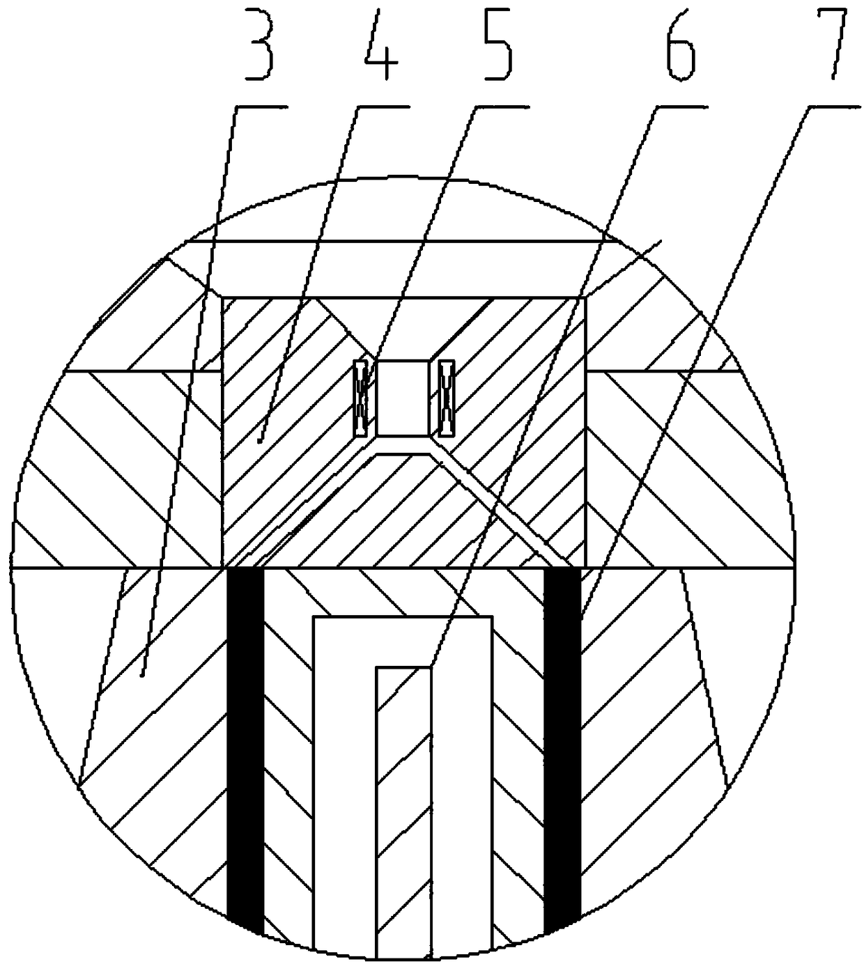
[0016] see figure 1 , figure 2 , image 3 , Figure 4 , a plastic nozzle injection molding mold with a flange, comprising a parting die 3, a core 17, and a push plate 16, the parting die 3 is composed of 3-4 mold petals, and the lower end of the middle part of the mold petals is provided with Slider 12, the outside of parting mold 3 is a tapered structure, and core 17 is provided in the cavity inside parting mold 3, and the outside of described core 17 bottom is provided with push plate 16, and described push plate 16 is positioned at The bottom of core 17, between described core 17, push plate 16, parting mold 3, be provided with injection mold cavity 7, described slide block 12 is arranged in the chute on the parting mold fixed plate 9, slide block The end of 12 is connected with outer cover plate 10 by spring 11, and described spring 11 is positioned at chute, and the outer side of described parting mold 3 bottom is provided with the sliding sleeve 8 that matches with i...


PUM


Abstract

The invention discloses an injection molding mold with a flange plastic exhausting pipe. A parting mold is composed of 3-4 pieces of mold petals. Sliding blocks are arranged at the lower ends of the middle parts of the mold petals. A core is arranged in a cavity which is located in the parting mold. A push plate is arranged on the outer side of the lower portion of the core. The push plate is arranged on the lower portion of the core. An injection molding cavity is formed between the core, the push plate and the parting mold. The sliding blocks are arranged in a sliding groove which is formedin a parting mold fixed plate, the end portions of the sliding blocks are connected with an outer sleeve plate through springs, the springs are located in the sliding groove, and a sliding sleeve which is matched with the conical surface of the parting mold is arranged on the outer side of the lower portion of the parting mold. The sliding sleeve is fixed on the lower portion of a conical cavity in an upper mold, a nozzle is fixed at the center of the upper portion of the upper mold, and a material inlet hole on the lower portion of the nozzle communicates with the upper end of the injection molding cavity. The parting mold fixed plate and the outer sleeve plate are fixed on a lower mold seat, and a material ejecting rod is connected to the lower portion of the push plate. The injection molding mold with the flange plastic exhausting pipe has the advantages of simple structure, high production efficiency and good product quality.

Description

technical field [0001] The invention belongs to the technical field of plastic moulds, in particular to an injection molding mold with a flanged plastic nozzle. Background technique [0002] Injection nozzles can be widely used in many fields such as HVAC, water supply and drainage, and chemical industry. Most injection nozzles are manufactured by injection molding. At present, the nozzle mold used for injection molding nozzles consists of an upper mold and a lower mold. When unloading after injection molding is completed, it is often performed by core-pulling, and the mold with core-pulling structure has the defects of complex structure and poor operation stability; Simultaneously existing spray tube injection mold also has many defects such as low production efficiency and poor product quality. Contents of the invention [0003] The purpose of the present invention is to overcome the above-mentioned deficiencies in the prior art, and to provide an injection molding mold...

Claims


Application Information

Patent Timeline
Patent Type & Authority Applications(China)
IPC IPC(8): B29C45/26B29C45/40B29C45/73
CPCB29C45/26B29C45/4005B29C45/73
Inventor 刘海建
Owner 安庆市洁达塑业有限公司
Learn More