Voltage-controlled oscillator circuit and phase-locked loop
A voltage-controlled oscillator and circuit technology, applied in the direction of electrical components, automatic power control, etc., can solve problems affecting the frequency accuracy of voltage-controlled oscillators, deteriorating phase noise and loop stability, increasing parasitic capacitance, etc., to achieve Effects of increased driving capability and frequency division accuracy, low power consumption, and increased tuning linearity
- Summary
- Abstract
- Description
- Claims
- Application Information
AI Technical Summary
Problems solved by technology
Method used
Image
Examples
Embodiment 1
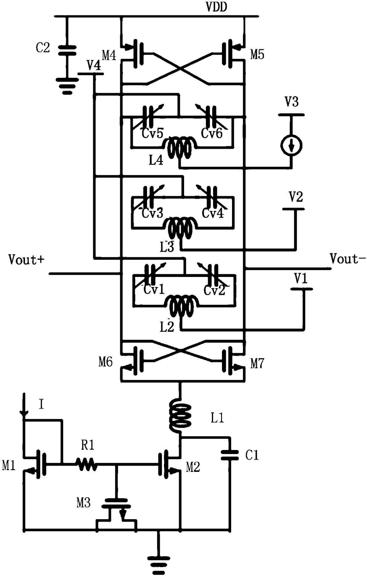
[0036] Such as figure 1 as shown, figure 1 A schematic structural diagram of a voltage-controlled oscillator circuit provided by an embodiment of the present invention; an embodiment of the present invention provides a voltage-controlled oscillator circuit, including a resonant cavity module and a power supply module. Specifically, the power supply module includes a first transistor M1, The second transistor M2, the third transistor M3, the first resistor R1, the first capacitor C1 and the first inductor L1, the gate and the drain of the first transistor M1 are respectively electrically connected to the external current source I, and the first A first resistor R1 is connected in series between the gate of the transistor M1 and the gate of the second transistor M2, and the gate of the third transistor M3 is electrically connected between the first resistor R1 and the second transistor M2 The connection node of the first transistor M1, the source of the second transistor M2, an...
Embodiment 2
[0047] On the basis of the above-mentioned embodiments, the phase-locked loop provided by the embodiments of the present invention is introduced in detail, as follows:
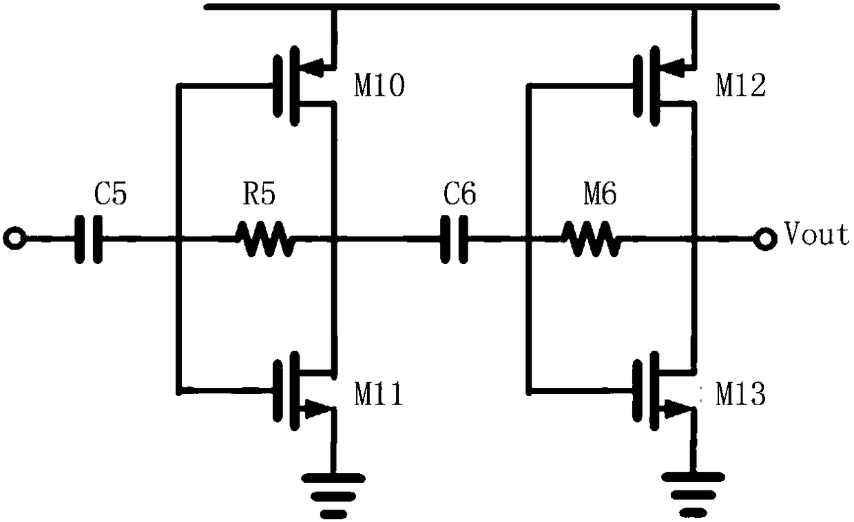
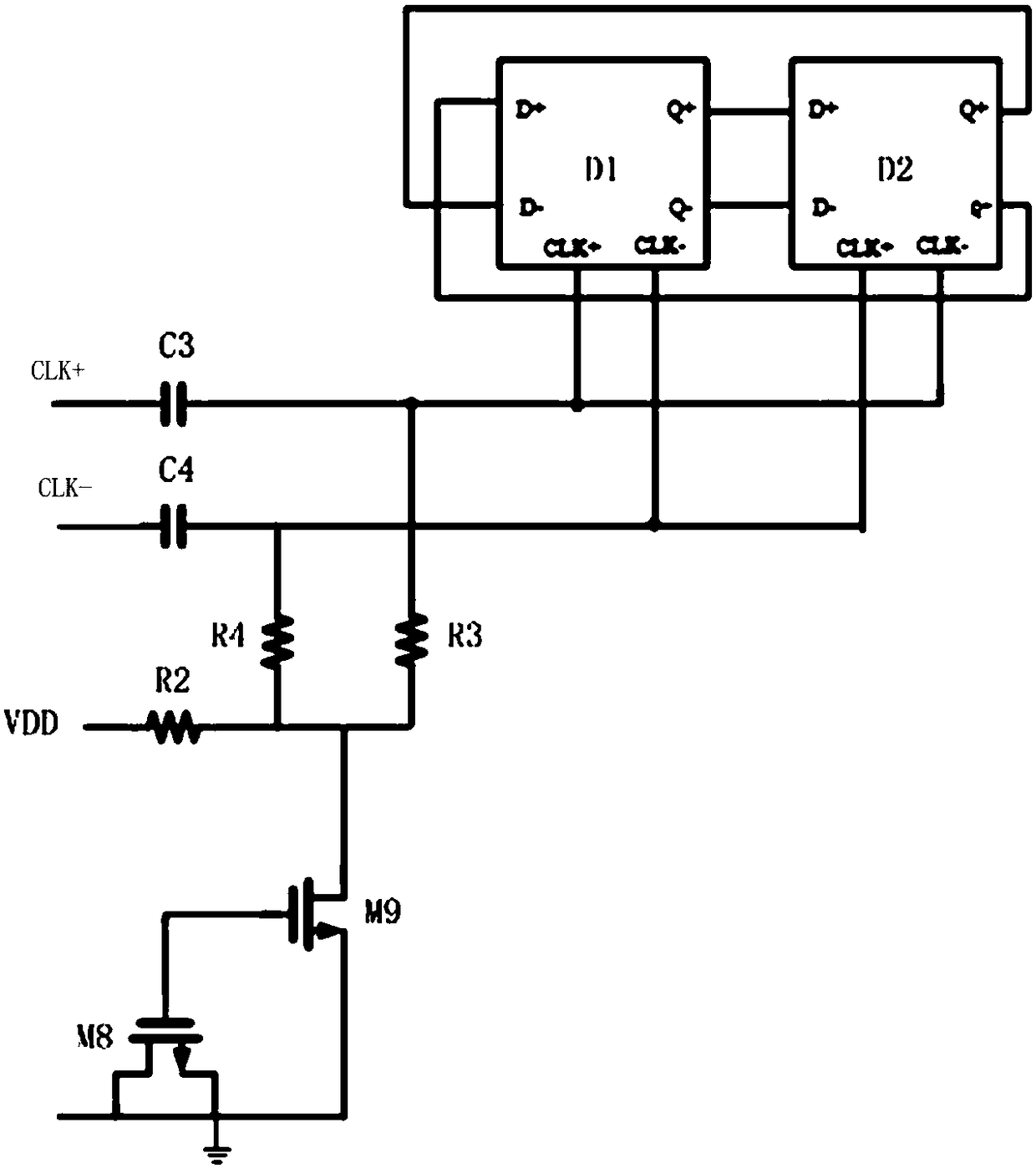
[0048] Such as Figure 2-6 as shown, figure 2 A schematic structural diagram of a buffer circuit provided by an embodiment of the present invention; image 3 A schematic structural diagram of a high-speed frequency-by-two circuit provided by an embodiment of the present invention; Figure 4 A schematic diagram of a circuit structure of a latch provided by an embodiment of the present invention; Figure 5 A schematic diagram of the circuit structure of the prescaler provided by the embodiment of the present invention; Figure 6 A schematic diagram of the circuit structure of the flip-flop provided by the embodiment of the present invention. An embodiment of the present invention provides a phase-locked loop, including a high-speed divide-by-two circuit, a prescaler, and the above-mentioned voltage-controll...
PUM
 Abstract
Description
Claims
Application Information
 - R&D
- Intellectual Property
- Life Sciences
- Materials
- Tech Scout
- Unparalleled Data Quality
- Higher Quality Content
- 60% Fewer Hallucinations
Browse by: Latest US Patents, China's latest patents, Technical Efficacy Thesaurus, Application Domain, Technology Topic, Popular Technical Reports.
© 2025 PatSnap. All rights reserved.Legal|Privacy policy|Modern Slavery Act Transparency Statement|Sitemap|About US| Contact US: help@patsnap.com


