
A continuous casting anti-clogging submerged nozzle

An immersion-type, anti-clogging technology, applied in casting equipment, casting melt containers, metal processing equipment, etc., can solve the problems of side hole nodulation, nozzle nodulation, blockage, etc., to prevent nodulation and blockage, improve casting Billet quality, ease of manufacture

Active Publication Date: 2020-02-11
NORTHEASTERN UNIV LIAONING
View PDF8 Cites 0 Cited by
  • Summary
  • Abstract
  • Description
  • Claims
  • Application Information

AI Technical Summary

Problems solved by technology

[0003] The purpose of the present invention is to solve the technical problem of nodulation and blockage of the side hole of the submerged nozzle during the continuous casting of molten steel of slab, bloom and round billet, and to avoid the non-metallic inclusions in the molten steel from adhering to the side hole of the submerged nozzle Nodules and blockages on the side walls

Method used


Image

  • A continuous casting anti-clogging submerged nozzle
  • A continuous casting anti-clogging submerged nozzle
  • A continuous casting anti-clogging submerged nozzle

Examples


Embodiment 1

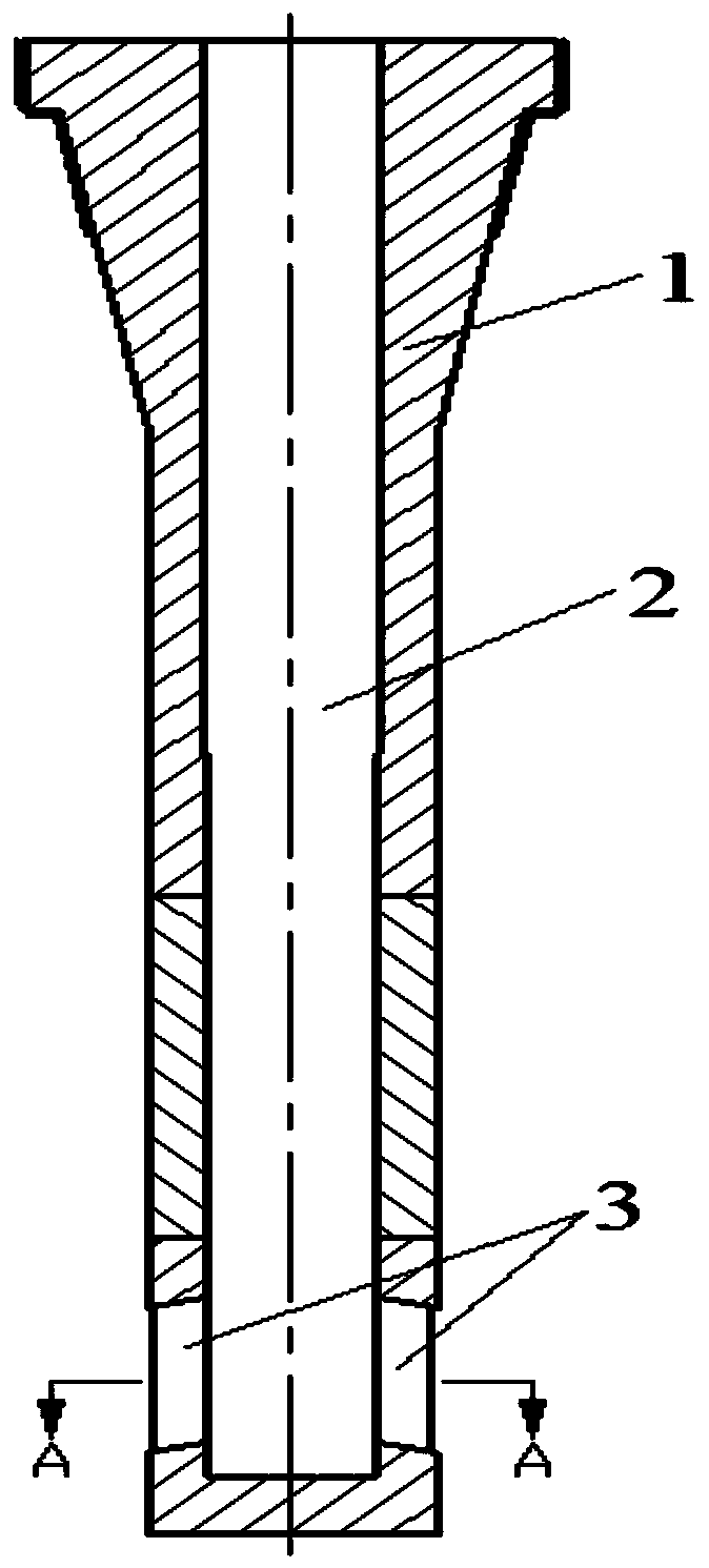
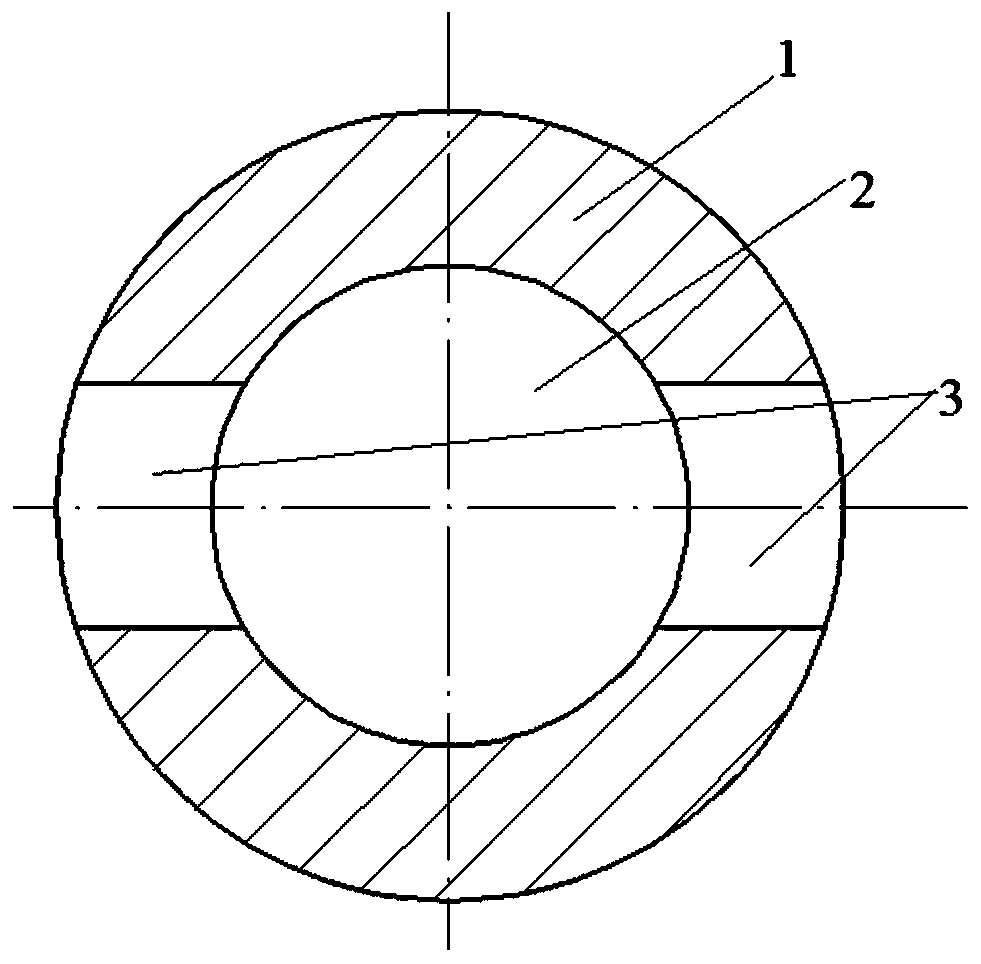
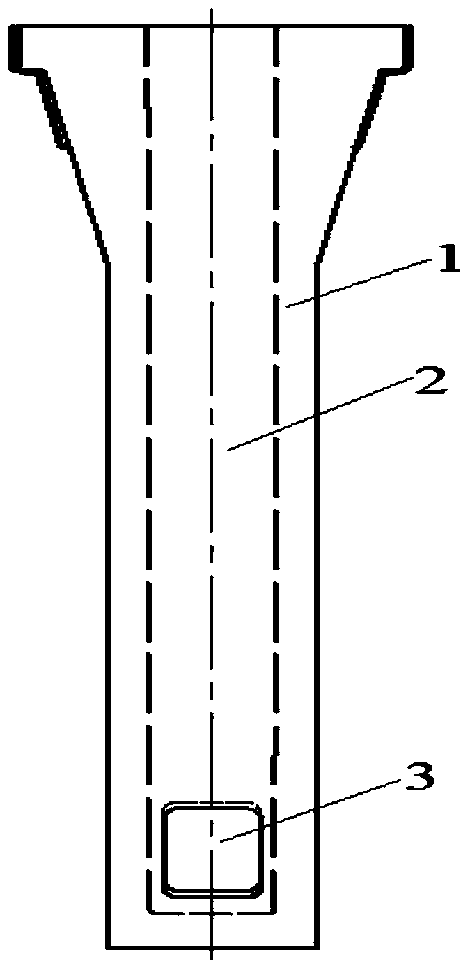
[0041] Such as Figure 4 , Figure 5 , Figure 6 As shown, the two side holes 3 of the anti-clogging submerged nozzle of the present invention are rectangular. The submerged nozzle is composed of a body 1, a main hole 2 and two rectangular holes 3 at the lower part of the side wall of the body, and the two side walls of the rectangular hole expand outwards with a straight side 6 with an angle α=20°, as shown in Figure 6 shown.

[0042] The bottom 4 of the side hole expands downward in an arc shape with a radius of R=50mm, and forms the lower side hole of the submerged nozzle with the top 7 of the side hole at a downward angle b=15°, such as Figure 4 shown.

Embodiment 2

[0044] Such as Figure 4 , Figure 5 , Figure 7 As shown, the two side holes 3 of the anti-clogging submerged nozzle of the present invention are rectangular. The submerged nozzle is composed of a main body 1, a main hole 2 and two rectangular side holes 3 at the bottom of the side wall of the body. Figure 7 ) expands outward, and the bottom of the side hole 4 ( Figure 4 ) expands downward in an arc with a radius of R=60mm, and is connected with the top 7 of the side hole at a downward angle b=14° ( Figure 4 ) constitute the lower side hole of the submerged nozzle.

Embodiment 3

[0046] Such as Figure 4 , Figure 8 , Figure 6 As shown, the two side holes 3 at the lower part of the anti-clogging submerged nozzle of the present invention are oval. The submerged nozzle is composed of a body 1, a main hole 2 and two oval holes 3 at the lower part of the side wall of the body. Figure 6 ) expands outward, and the bottom of the side hole 4 ( Figure 4 ) expands downward in an arc with a radius of R=40mm, and is connected with the top 7 of the side hole at a downward angle b=15° ( Figure 4 ) constitute the lower side hole of the submerged nozzle.


PUM


Abstract

The invention belongs to the field of high-temperature molten steel continuous casting, and relates to a continuous casting anti-clogging immersed nozzle, which includes a body, a main hole and a side hole; the main hole is located inside the body, and the side holes are located on both sides of the body and the main hole. Connected; there are no less than one pair of side holes. The side hole is designed so that both side walls expand outward in an arc with an angle α or a radius r, and the bottom of the side hole expands downward in an arc with a radius R, and forms an immersion with the top of the side hole at a downward angle b. The lower side hole of the nozzle. This new type of anti-clogging immersed nozzle allows the non-metallic inclusion particles in the liquid steel to directly flow out of the side holes of the immersed nozzle when the molten steel flows through the side holes of the immersed nozzle, thus avoiding non-metallic inclusions in the liquid steel. The objects collide with the side wall of the immersed nozzle side hole, thereby preventing inclusions from adhering to the side wall of the side hole, effectively preventing nodulation and clogging of the immersed nozzle side hole, and ensuring smooth continuous casting production.

Description

technical field [0001] The invention belongs to the field of high-temperature molten steel continuous casting, and relates to an anti-clogging submerged nozzle for continuous casting. Background technique [0002] In the continuous casting of molten steel at high temperature, especially when continuously casting low-carbon aluminum-killed steel, steel with high aluminum content, rare earth-containing steel and titanium-containing steel, there are more non-metallic inclusions in the molten steel , when the molten steel containing tiny non-metallic inclusions enters the crystallizer from the continuous casting tundish through the submerged nozzle, the inclusions in the molten steel adhere to the side wall of the straight-walled side hole at the lower part of the submerged nozzle , with the progress of molten steel casting, the number of inclusions adhering to the side wall of the lower side hole of the submerged nozzle gradually increases, forming nodules, resulting in a decre...

Claims


Application Information

Patent Timeline
Patent Type & Authority Patents(China)
IPC IPC(8): B22D41/50
CPCB22D41/50
Inventor 钟良才季伟烨贾丹林孙建月杜文斌
Owner NORTHEASTERN UNIV LIAONING
Learn More