
A single-mode optical fiber with ultra-low loss and large effective area and its manufacturing method

A single-mode optical fiber, effective area technology, applied in the direction of manufacturing tools, cladding optical fiber, glass manufacturing equipment, etc., can solve the problems affecting the reduction of optical fiber transmission loss, affecting the strength and service life of optical fiber, and difficult to achieve low-loss optical fiber. Achieve the effects of increasing the effective area, superior bending resistance, and ultra-low loss effective area

Active Publication Date: 2020-05-05
FENGHUO COMM SCI & TECH CO LTD
View PDF1 Cites 0 Cited by
  • Summary
  • Abstract
  • Description
  • Claims
  • Application Information

AI Technical Summary

Problems solved by technology

Therefore, in the actual drawing process, the high-temperature viscosity matching of the optical fiber material components leads to incomplete optical fiber structure, which seriously affects the reduction of optical fiber transmission loss, and it is difficult to realize the manufacture of low-loss optical fibers; on the other hand, the high-temperature viscosity mismatch is due to The core material has different characteristic temperatures such as glass softening temperature. During the wire drawing process, different specific temperatures of the core will cause a large residual stress in the optical fiber
This not only destroys the designed waveguide structure, but also affects the strength and service life of the fiber

Method used


Image

  • A single-mode optical fiber with ultra-low loss and large effective area and its manufacturing method
  • A single-mode optical fiber with ultra-low loss and large effective area and its manufacturing method
  • A single-mode optical fiber with ultra-low loss and large effective area and its manufacturing method

Examples


Embodiment 1

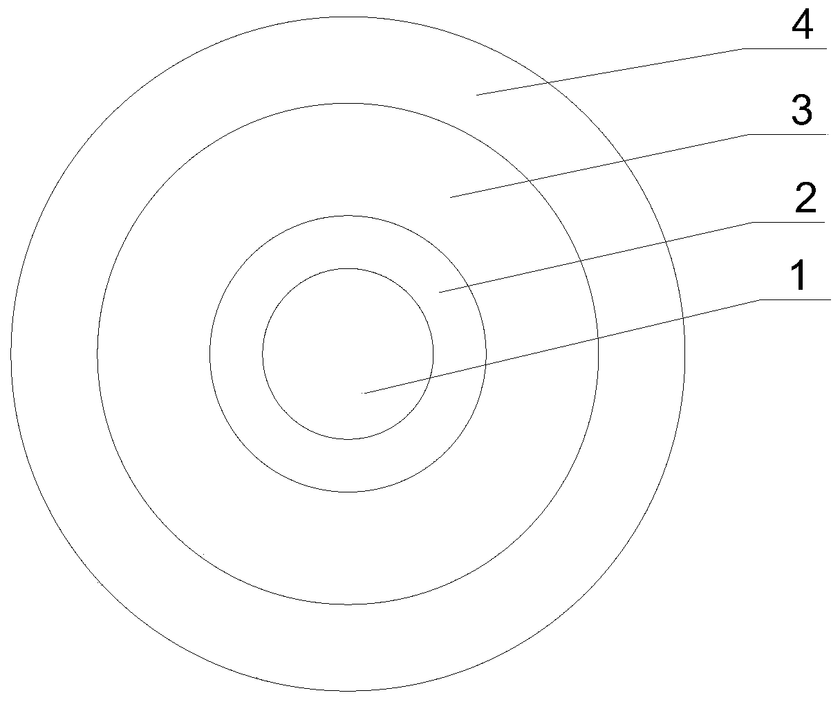
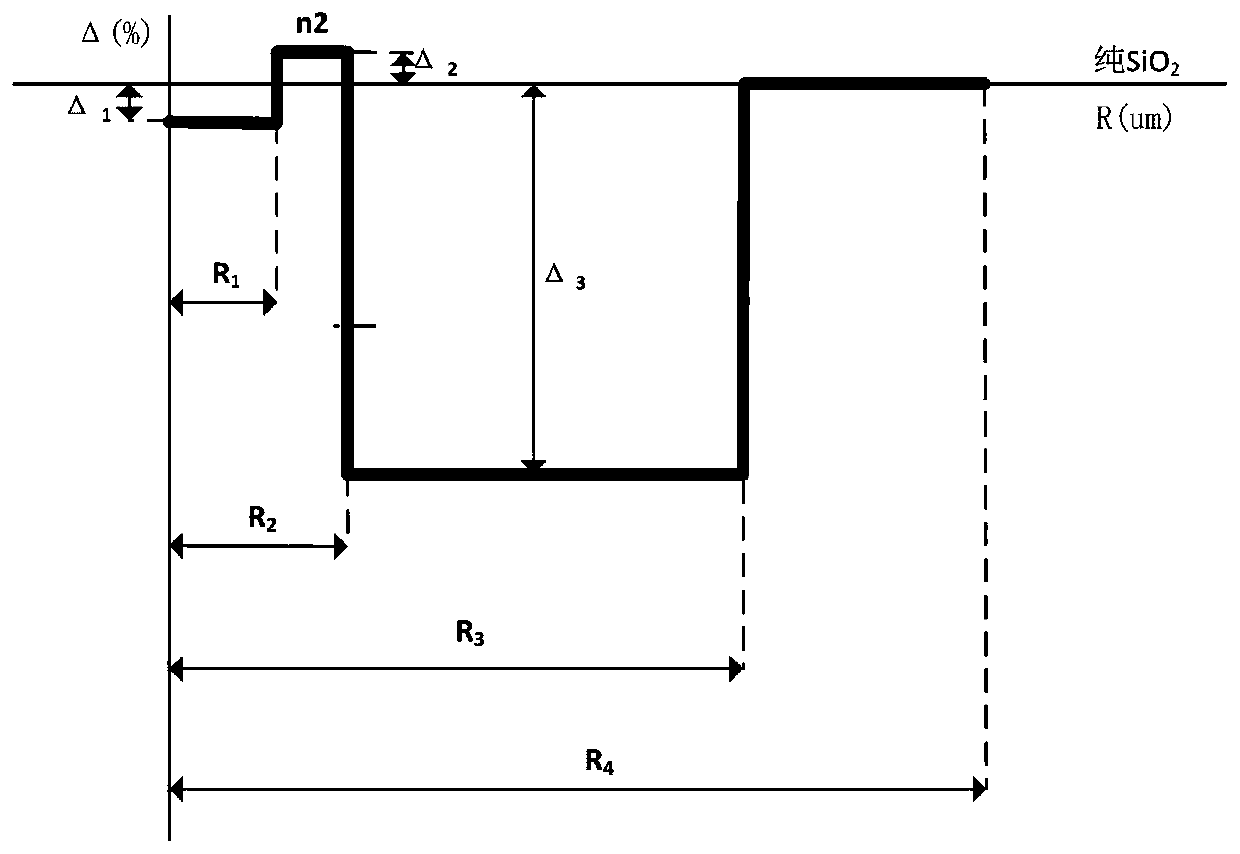
[0047] see figure 1 and figure 2 As shown, the embodiment of the present invention provides a single-mode optical fiber with ultra-low loss and large effective area. The bare optical fiber includes a core layer and a cladding layer from the inside to the outside in sequence, and the core layer includes an inner core layer 1 and a cladding layer that are sequentially arranged from the inside to the outside. Radius R of outer core layer 2 and inner core layer 1 1 1.5-3μm, the relative refractive index difference Δ of the inner core layer 1 1 -0.01%≤Δ 1 ≤0, the radius R of the outer core layer 2 2 5-6 μm, the relative refractive index difference Δ of the outer core layer 2 2 0≤Δ 2 ≤0.05%; the core layer is hardly doped with germanium, and the core layer is a silica glass layer co-doped with fluorine and alkali metal oxides; the cladding layer includes a sunken cladding layer 3 and an outer cladding layer 4 arranged sequentially from the inside to the outside, and the sunken...

Embodiment 2

[0066] This embodiment provides a method for manufacturing the above-mentioned ultra-low loss and large effective area single-mode optical fiber, which includes the following steps: using plasma chemical vapor deposition to deposit on a quartz reaction tube to make an optical fiber preform, and the optical fiber preform is made of SiCl 4 、GeCl 4 、C 2 f 6 As the raw material, the designed optical rod profile is prepared by changing the gas flow rate and ratio, as well as the moving speed of the reaction zone and the number of deposition times during the production process, and a certain concentration of alkali metal oxide is added during the rod forming process, and oxygen is introduced at the same time The reaction is carried out to remove water, and finally the high temperature is melted and shrunk into a rod to prepare an alkali metal-doped optical fiber preform rod, and the alkali metal-doped optical fiber preform rod is subjected to wire drawing treatment.

[0067] Where...

Embodiment 3~7

[0071] In the present invention, the PCVD deposition method is used to effectively control the distribution of the refractive index of each layer. The following five specific examples of Examples 3-7 are used to illustrate.

[0072] Table 1. Refractive index profile and doping material content of the single-mode optical fiber of the present invention

[0073]

[0074]

[0075] Table 2, the main performance parameters of the single-mode optical fiber of the present invention

[0076]

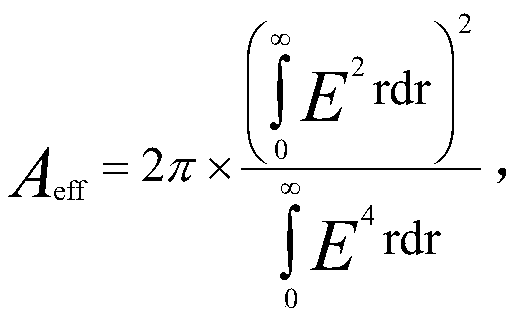
[0077] As can be seen from the above Table 2, the single-mode optical fiber provided by the present invention has a mode field diameter of 12.1-13um at a working wavelength of 1550nm, which can not only reduce the power density of light, but also increase the effective area of ​​the optical fiber. Area higher than 122um 2 , even up to 130um 2 about.

[0078] In the single-mode optical fiber provided by the present invention, the radius R of the inner core layer 1 1 1.5-3 μm, the radi...


PUM

PropertyMeasurementUnit
radiusaaaaaaaaaa
radiusaaaaaaaaaa
radiusaaaaaaaaaa

Abstract

The invention discloses a single-mode optical fiber with ultra-low loss and large effective area and its manufacturing method. The bare optical fiber includes a core layer and a cladding layer sequentially from the inside to the outside, and the core layer includes an inner core layer and a cladding layer arranged sequentially from the inside to the outside. outer core layer, the radius R of the inner core layer 1 is 1.5-3 μm, and the relative refractive index difference Δ of the inner core layer 1 ‑0.01%≤Δ 1 ≤0, the radius R of the outer core layer 2 is 5-6 μm, and the relative refractive index difference Δ of the outer core layer 2 0≤Δ 2 ≤0.05%; the core layer is hardly doped with germanium, and the core layer is a silica glass layer co-doped with fluorine and alkali metal oxide; the cladding layer includes a sunken cladding layer and an outer cladding layer arranged in sequence from the inside to the outside layer, the sunken cladding radius R 3 is 40-50 μm, the relative refractive index difference Δ of the depressed cladding 3 ‑0.25% ≤ Δ 3 ≤‑0.15% of the sunken cladding radius R 3 with the outer core radius R 2 The ratio of R 3 / R 2 ≥8, the outer cladding radius R 4 is 62.5 μm, and the outer cladding layer is a pure silica glass layer. The invention can reduce the attenuation coefficient and increase the effective area.

Description

technical field [0001] The invention relates to the field of optical fibers, in particular to an ultra-low loss large effective area single-mode optical fiber and a manufacturing method thereof. Background technique [0002] With the emergence of coherent transmission technology, in the field of optical fiber transmission, some important indicators that originally limited long-distance, large-capacity and high-speed transmission are no longer the main limiting factors. In the future transmission system, the indicators of dispersion and polarization mode dispersion will be further relaxed. However, the growth of transmission capacity and distance requires higher fiber input power and lower fiber loss to meet the requirement of resolvable signal-to-noise ratio. With the increase of fiber power, nonlinear effects such as phase modulation, cross-phase modulation, and four-wave mixing will inevitably occur in the fiber core layer, especially the stimulated Brillouin scattering e...

Claims


Application Information

Patent Timeline
Patent Type & Authority Patents(China)
IPC IPC(8): G02B6/02G02B6/036C03B37/018C03B37/027
CPCG02B6/02009G02B6/03611G02B6/03627C03B37/018C03B37/027C03B2203/24C03B2203/32G02B6/02019C03B2201/50C03B37/01838C03B37/01807C03B2201/12C03B2201/31G02B6/03694
Inventor 喻煌赵梓森骆城张一弛
Owner FENGHUO COMM SCI & TECH CO LTD
Learn More