
Catalytically cracked oil slurry furfural extracted oil hydrogenation catalyst, and preparation method and applications thereof

A technology for catalytic cracking of oil slurry and furfural extraction of oil, which is applied in physical/chemical process catalysts, molecular sieve catalysts, chemical instruments and methods, etc., can solve problems such as no extraction of oil, and achieve high hydrodesulfurization and active metal utilization. , the effect of large specific surface area

Active Publication Date: 2018-08-28
PETROCHINA CO LTD
View PDF13 Cites 4 Cited by
  • Summary
  • Abstract
  • Description
  • Claims
  • Application Information

AI Technical Summary

Problems solved by technology

[0005] At present, there is no special hydrofining catalyst for extracted oil in the industry, and conventional wax oil and residual oil hydrogenation catalysts are mostly used

Method used


Image

  • Catalytically cracked oil slurry furfural extracted oil hydrogenation catalyst, and preparation method and applications thereof
  • Catalytically cracked oil slurry furfural extracted oil hydrogenation catalyst, and preparation method and applications thereof

Examples


Embodiment 1

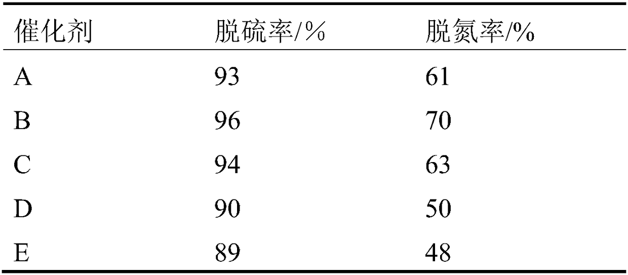
[0033]Take 100g of pseudoboehmite, 11.2g of TS-1 molecular sieve, 1.4g of zirconia, and 1.4g of graphene, and mix them evenly. Add 2.8g of scallop powder, mix evenly, dropwise add an aqueous solution containing 2.8g of nitric acid and 2.8g of citric acid, knead, extrude into a clover shape of 1.5mm, freeze-dry, and then roast at 550°C for 4h to make a carrier. Reuse Mn 6 [WMn 3 (H 2 O) 2 (ZnW 9 o 34 ) 2 ] The prepared impregnating solution was impregnated with equal volume (see Table 1 for the amount of active components supported in the catalyst), freeze-dried, and calcined at 300°C for 6h to obtain catalyst A.

Embodiment 2

[0035] Take 100g of pseudoboehmite, 105g of TS-1 molecular sieve, 35g of zirconia, and 17.5g of graphene, and mix them evenly. Add 17.5g of scallop powder, mix evenly, add dropwise an aqueous solution containing 17.5g of nitric acid and 17.5g of citric acid, knead, extrude into a clover shape of 1.5mm, freeze-dry, and then roast at 550°C for 4h to make a carrier. Reuse Co 6 [WCo 3 (H 2 O) 2 (ZnW 9 o 34 ) 2 ] The prepared impregnating solution was impregnated with equal volume (see Table 1 for the amount of active components supported in the catalyst), freeze-dried, and calcined at 300° C. for 5 h to obtain catalyst B.

Embodiment 3

[0037] Take 100g of pseudoboehmite, 35g of TS-1 molecular sieve, 12.25g of zirconia, and 5.25g of graphene, and mix them evenly. Add 7g of scallop powder, mix evenly, dropwise add an aqueous solution containing 7g of nitric acid and 7g of citric acid, knead, extrude into a clover shape of 1.5mm, freeze-dry, and then roast at 550°C for 4h to make a carrier. Use Ni again 6 [WNi 3 (H 2 O) 2 (ZnW 9 o 34 ) 2 ] The prepared impregnating solution was impregnated with equal volume (see Table 1 for the amount of active components supported in the catalyst), freeze-dried, and calcined at 550°C for 2h to obtain catalyst C.


PUM

PropertyMeasurementUnit
specific surface areaaaaaaaaaaa
diameteraaaaaaaaaa

Abstract

The invention discloses a catalytically cracked oil slurry furfural extracted oil hydrogenation catalyst, and a preparation method and applications thereof. The catalytically cracked oil slurry furfural extracted oil hydrogenation catalyst comprises a carrier and an active component; the active component is loaded by the carrier; the carrier is a composite carrier comprising TS-1 molecular sieve,gamma-Al2O3, ZrO2, and graphene; the active component is loaded onto the carrier through one time or multiple time dipping; an adopted dipping solution is a heteropoly acid solution; 100wt% of the catalytically cracked oil slurry furfural extracted oil hydrogenation catalyst comprises 1 to 30wt% of TS-1 molecular sieve, 20 to 50wt% of gamma-Al2O3, 1 to 10wt% of ZrO2, 1 to 5wt% of graphene, and 30to 40wt% of the active component. The catalytically cracked oil slurry furfural extracted oil hydrogenation catalyst is high in hydrodesulfurization and denitrification activity, and is suitable to betaken as a catalytically cracked oil slurry furfural extracted oil hydrogenation catalyst.

Description

technical field [0001] The invention relates to a catalytic cracking oil slurry furfural refined oil hydrogenation catalyst, which is suitable for the hydrogenation process of catalytic cracking oil slurry furfural refined oil in the field of petroleum refining. Background technique [0002] Using furfural as a solvent, the alkanes and aromatics in the catalytic cracking oil slurry are separated to obtain aromatic-rich extracted oil and alkane-rich raffinate oil. High-purity heavy aromatics can produce high value-added aromatics products, and the alkane-rich part is a high-quality catalytic cracking raw material, which can be re-smelted to significantly improve economic benefits. [0003] However, the sulfur and nitrogen content in the extracted oil and raffinate oil are relatively high, and subsequent processing has certain difficulties. After hydrofining the raffinate oil as a high-quality catalytic cracking raw material, it can not only produce low-sulfur gasoline and di...

Claims


Application Information

Patent Timeline
Patent Type & Authority Applications(China)
IPC IPC(8): B01J29/89C10G45/12C10G45/10
CPCB01J29/89B01J2229/18C10G45/10C10G45/12
Inventor 徐铁钢孙发民马宝利张浩王磊倪术荣温广明宋金鹤张国甲纪魏于强王丹方磊谭明伟徐伟池姜维丛丽茹王刚郭金涛郭立艳
Owner PETROCHINA CO LTD
Learn More