
Clearing device of machining iron scraps

A technology for machining and cleaning devices, applied in metal processing equipment, metal processing mechanical parts, manufacturing tools, etc., can solve problems such as time-consuming, complicated operation, and wet iron filings.

Inactive Publication Date: 2018-08-21
肇庆智达自动化设备有限公司
View PDF0 Cites 5 Cited by
  • Summary
  • Abstract
  • Description
  • Claims
  • Application Information

AI Technical Summary

Problems solved by technology

[0004] A large amount of iron filings will be produced during mechanical processing. The current scrap iron scrap cleaning device has the disadvantages of unclean cleaning, time-consuming, heavy workload, low work efficiency, and complicated operation. Therefore, it is urgent to develop a cleaning and time-consuming Small amount, high work efficiency, and simple operation of machining waste. Therefore, the tiny components in the iron filings are mixed with the large iron filings, and the iron filings are wet and watery after cleaning; therefore, those skilled in the art provide a mechanical processing waste iron scrap Cleaning device, to solve the problems raised in the above-mentioned background technology

Method used


Image

  • Clearing device of machining iron scraps
  • Clearing device of machining iron scraps

Examples


Embodiment Construction

[0018] The following will clearly and completely describe the technical solutions in the embodiments of the present invention with reference to the accompanying drawings in the embodiments of the present invention. Obviously, the described embodiments are only some, not all, embodiments of the present invention. Based on the embodiments of the present invention, all other embodiments obtained by persons of ordinary skill in the art without making creative efforts belong to the protection scope of the present invention.

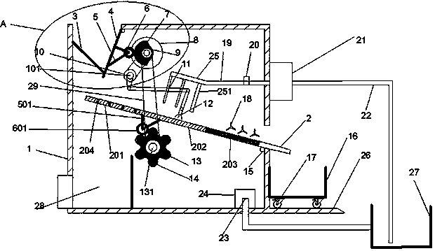
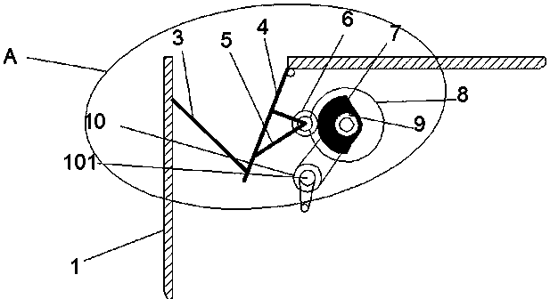
[0019] see Figure 1~2 , in the embodiment of the present invention, a mechanical processing waste iron chip cleaning device includes a box body 1 and a vibrating plate 2, a hopper 3 is arranged on the left side of the upper part of the box body 1, a rotating plate 4 is arranged on the hopper 3, and the rotating plate 4. The upper end is hinged on the top inner wall of the box body 1. Two symmetrical tripods a5 are fixedly connected to the right side of the ro...


PUM


Abstract

The invention discloses a clearing device of machining iron scraps, which comprises a box body, a first rotary shaft, a second rotary shaft, a petal-shaped cam and a vibrating plate, wherein a hopperis arranged on the left side of the upper part of the box body; a rotary plate is arranged on the hopper and provided with a roller a; a cam is matched with the right side of the roller a in a rollingmanner; the cam is fixedly connected onto an output shaft of a motor; the first rotary shaft is fixedly connected with a crank and rocker mechanism; a slide fork is arranged at the lower end of a rocker of the crank and rocker mechanism; the second rotary shaft is fixedly connected with the petal-shaped cam; an inner cavity of the box body is provided with the vibrating plate inclined to the bottom right; the part, located in the inner cavity of the box body, of the vibrating plate is divided into three sections: a screening section, a clearing section and a drying section sequentially from left to right; a roller b is arranged below the clearing section and matched with the petal-shaped cam; and a water sprayer is arranged on the clearing section and communicated with a pool through a water spray pipe, a pump and a water suction pipe. The device can achieve screening, clearing and drying of the iron scraps simultaneously and is convenient and practical.

Description

technical field [0001] The invention relates to a cleaning device, in particular to a cleaning device for machining waste iron chips. Background technique [0002] Machinery refers to the general term for machines and mechanisms. Machinery is a tool device that can help people reduce the difficulty of work or save labor. [0003] Objects like chopsticks, brooms, and tweezers can be called machines, they are simple machines. A complex machine is composed of two or more simple machines. These more complex machines are usually called machines. From the point of view of structure and motion, there is no difference between a mechanism and a machine, and it is generally called a machine. [0004] A large amount of iron filings will be produced during mechanical processing. The current scrap iron scrap cleaning device has the disadvantages of unclean cleaning, time-consuming, heavy workload, low work efficiency, and complicated operation. Therefore, it is urgent to develop a cl...

Claims


Application Information

Patent Timeline
IPC IPC(8): B23Q11/00
CPCB23Q11/0042
Inventor 陆仲权
Owner 肇庆智达自动化设备有限公司
Learn More