
Machining method of irregular shell component inner cavity bottom annular groove

A processing method and technology of annular grooves, applied in the field of processing annular grooves at the bottom of the inner cavity of irregular shell components, can solve the problems of poor processing quality, poor processing rigidity, low processing efficiency, etc., and achieve stable processing state and processing stability Good, good surface quality effect

Active Publication Date: 2018-08-17
重庆天骄航空动力有限公司
View PDF8 Cites 6 Cited by
  • Summary
  • Abstract
  • Description
  • Claims
  • Application Information

AI Technical Summary

Problems solved by technology

[0003] (1) Poor processing rigidity; usually manifested as poor clamping rigidity of the workpiece and poor rigidity of the processing tool
The poor clamping rigidity is caused by the irregularity of the workpiece and the special structure of the fixture; the poor rigidity of the machining tool is caused by the long overhang of the tool determined by the position of the deep and narrow groove
[0004] (2) The machining of the workpiece is unstable; since the shell member to be processed is not a ring structure, the workpiece rotation process is an eccentric motion during the turning process, and the machining state of the workpiece is unstable
[0005] (3) The processing quality is poor; due to the poor clamping rigidity of the workpiece, the unstable processing state and the poor rigidity of the processing tool, vibrations are easily generated during the processing process, and the final result is that the surface quality and dimensional accuracy of the annular groove cannot meet the requirements
[0006] (4) Low processing efficiency; the clamping state of the workpiece limits the rotation speed of the workpiece, and repeated turning is required to meet the accuracy requirements, resulting in low processing efficiency and is not conducive to mass production
[0010] However, the former processing method is suitable for machining radial narrow grooves (non-annular grooves) on annular casing components, and the latter processing method is suitable for processing inclined grooves on the inner wall of the casing of aero-engines. Both processing methods Not suitable for processing the annular groove at the bottom of the inner cavity of irregular shell components

Method used


Image

  • Machining method of irregular shell component inner cavity bottom annular groove
  • Machining method of irregular shell component inner cavity bottom annular groove
  • Machining method of irregular shell component inner cavity bottom annular groove

Examples


Embodiment Construction

[0046] The technical solutions of the present invention will be clearly and completely described below in conjunction with the accompanying drawings.

[0047] The method for processing the annular groove at the bottom of the inner cavity of the irregular shell member according to the present invention is characterized in that it includes the following steps:

[0048] The first step is to customize the tool;

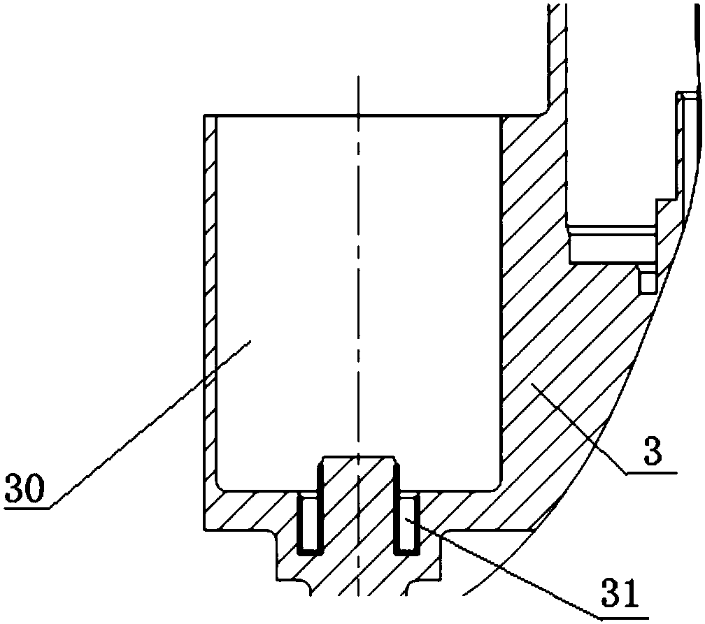
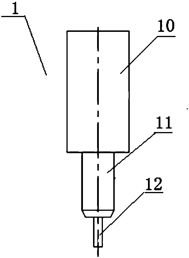
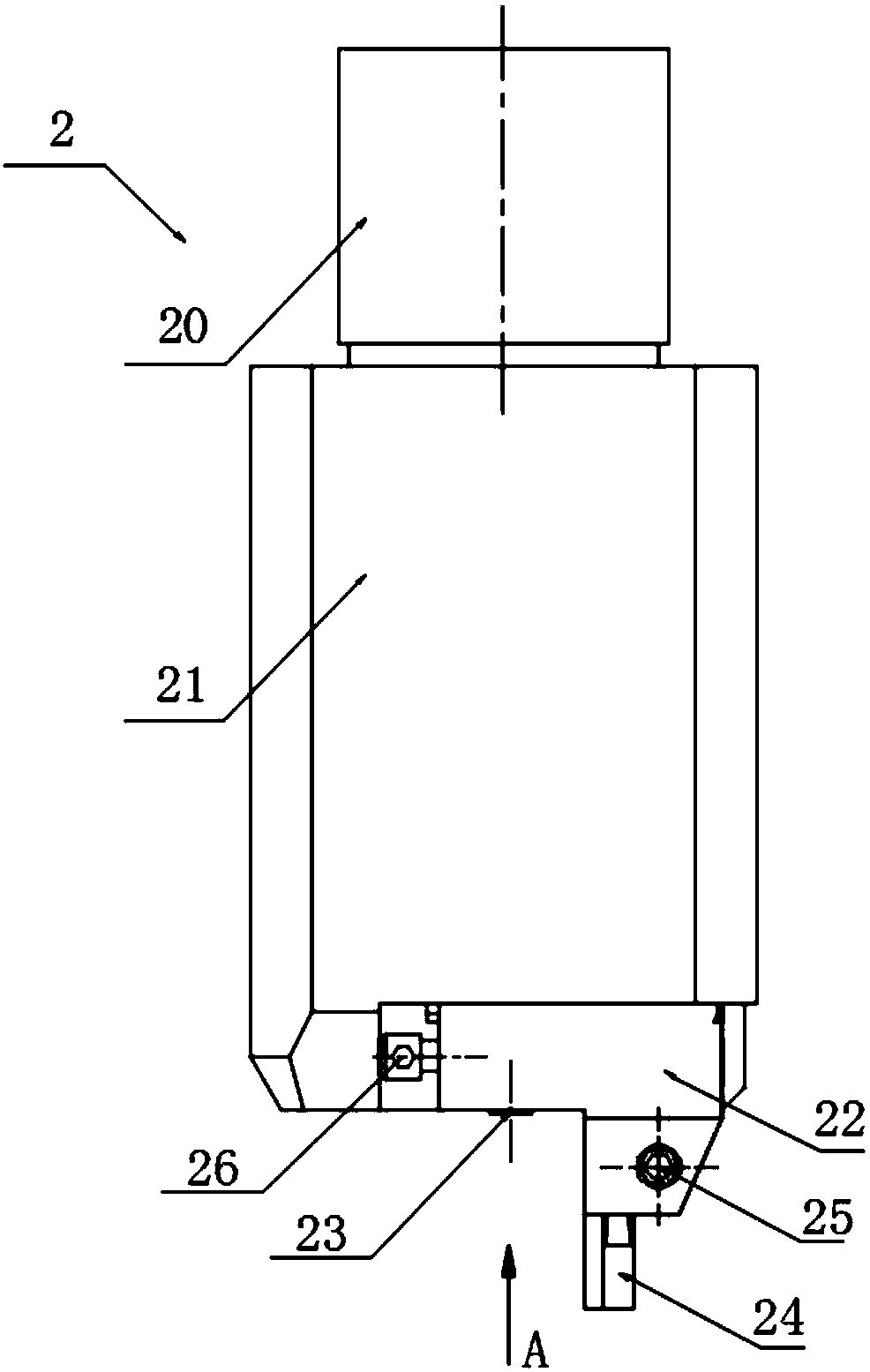
[0049] 1) According to the size and accuracy requirements of the annular groove 31 that needs to be processed at the bottom of the inner cavity 30 of the irregular shell member 3, the milling cutter 1 for rough machining the annular groove is customized, see figure 1 with figure 2The milling cutter 1 is composed of a shank 10, a cutter body 11 and a cutting edge 12; The diameter of the ring groove is smaller than the width of the ring groove, and the unilateral margin of the ring groove after milling is guaranteed to be 0.5mm (mm);

[0050] 2) According to the size an...


PUM


Abstract

The invention relates to a machining method of an irregular shell component inner cavity bottom annular groove. The machining method comprises following steps that firstly, according to the size and precision needs of the annular ring groove required to be machined in the bottom of an inner cavity of an irregular shell component, a milling cutter used for rough machining of the annular groove anda turn milling knife used for semi finishing of the annular groove and the finishing of the annular groove are customized; secondly, the turn milling knife is subject to trial cutting and adjusting; thirdly, the irregular shell component is clamped on a worktable of a numerical control machining center, and is fixed; fourthly, the annular groove is roughly machined; fifthly, the annular groove issubject to semi-finishing operation; sixthly, the annular groove is subject to finishing. The method is good in machining stability, the machined annular groove is good in surface quality, high in size precision, high in cutting efficiency, capable of achieving large-batch production and good in consistency.

Description

technical field [0001] The invention relates to an accessory of an aero-engine, and relates to a processing method for an annular groove at the bottom of an inner chamber of an irregular casing member. Background technique [0002] In the processing of mechanical parts, especially in some shell components with cavities, there are often some deep and narrow annular groove structures. Commonly found in cavities of aero-engine accessory cases. This annular groove structure is designed to be used in conjunction with parts, not only in a special position, but also requires high dimensional accuracy and roughness, and also has requirements for shape and position tolerances such as coaxiality, cylindricity, and roundness. The material of the shell member with the cavity is generally aluminum-magnesium alloy, which has high viscosity and is difficult to process. For such annular grooves, the traditional processing method is to customize special fixtures and use ordinary lathes or ...

Claims


Application Information

Patent Timeline
Patent Type & Authority Applications(China)
IPC IPC(8): B23P15/00
CPCB23P15/00
Inventor 杨文广郭万军郭向飞
Owner 重庆天骄航空动力有限公司
Learn More