
Embedded groove type clamp spring assembly and method for drilling hard alloy materials by using embedded groove type clamp spring assembly

A technology of hard alloy and circlip, which is applied in the direction of boring/drilling, drilling/drilling equipment, metal processing equipment, etc. It can solve the problems of damage to parts, inconvenient disassembly, breakage, etc., and achieves favorable The effect of processing, complete appearance and stable state

Inactive Publication Date: 2012-10-03
SHANGHAI MARITIME UNIVERSITY
View PDF6 Cites 0 Cited by
  • Summary
  • Abstract
  • Description
  • Claims
  • Application Information

AI Technical Summary

Problems solved by technology

However, the overall processing force strength is still not high enough, and the connection between the top kit and the shaft is only supported by spot welding, so it is difficult to ensure a stable state during the entire processing
Especially when the drilling speed of the spindle of the drilling machine is high, the parts in the processing assembly are prone to "breakage" or even "throwing" out when the winding degree increases.
cause injury to the operator
[0011] Also, although the spot welds "join" the tip kit and shaft piece welded together, in practice it is extremely inconvenient to disassemble
If the force is not appropriate, it will cause friction between the top kit and the shaft, causing the size of each component to be deformed, resulting in damage to the fittings of the components, resulting in assembly loss
[0012] Therefore, it is difficult for the above three traditional processes to complete the drilling process for cemented carbide materials.

Method used


Image

  • Embedded groove type clamp spring assembly and method for drilling hard alloy materials by using embedded groove type clamp spring assembly
  • Embedded groove type clamp spring assembly and method for drilling hard alloy materials by using embedded groove type clamp spring assembly
  • Embedded groove type clamp spring assembly and method for drilling hard alloy materials by using embedded groove type clamp spring assembly

Examples


Embodiment Construction

[0045] The present invention will be further elaborated below by describing a preferred specific embodiment in detail in conjunction with the accompanying drawings.

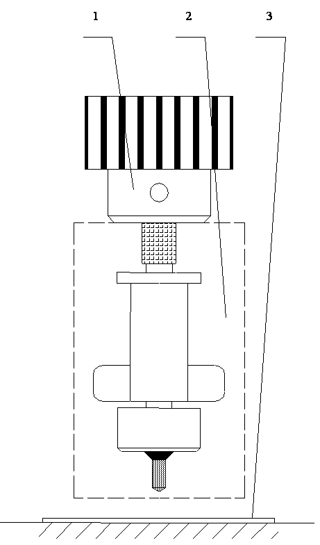
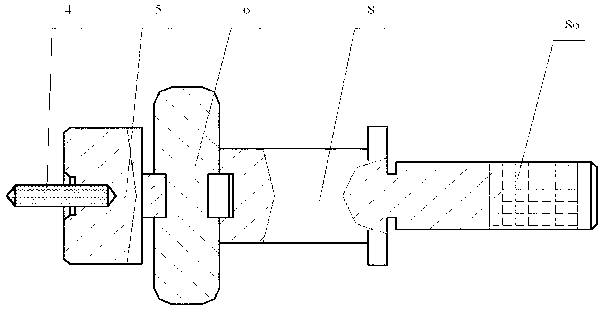
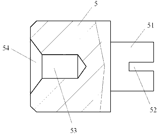
[0046] Such as figure 1 with figure 2 As shown, the recessed snap ring assembly 2 includes: a drill bit 4, in this embodiment, the drill bit 4 is made of tungsten steel material; the top sleeve 5 connected with the drill bit 4; the rod connected with the top sleeve 5 through interference fit Body part 8, the outer wall of the shaft part 8 is clamped by the external wrench drill chuck 1, so as to fix the embedded groove type circlip assembly to drill the hard alloy material with a thickness not greater than 5mm; set it on the top kit through the embedded groove 5 and the snap ring positioning piece 6 between the shaft part 8. In this embodiment, both the top sleeve 5 and the shaft part 8 are made of Cr12 steel and heat-treated to obtain higher surface hardness and strength.

[0047] Among them, such as image...


PUM

PropertyMeasurementUnit
thicknessaaaaaaaaaa

Abstract

The invention discloses an embedded groove type clamp spring assembly and a method for drilling hard alloy materials by using the embedded groove type clamp spring assembly. The embedded groove type clamp spring assembly comprises a drilling bit, a top end external member, a rod body piece and a clamp spring positioning piece. The method for drilling hard alloy materials by using the embedded groove type clamp spring assembly comprises the following steps of: step 1, fixing the hard alloy materials; step 2, clamping the embedded groove type clamp spring assembly through a spanner drill chuck; and step 3, drilling the hard alloy materials. The embedded groove type clamp spring assembly and the method for drilling hard alloy materials by using the embedded groove type clamp spring assembly can effectively drill through holes, the appearance of the through holes is complete, the whole machining process is stable, and machining is facilitated.

Description

technical field [0001] The invention relates to a drilling process and an embedded circlip assembly for hard alloy materials with a thickness not greater than 5 mm in the processing of molds in the clamp bed, in particular to an embedded circlip assembly and its application to cemented carbide materials. The method of drilling. Background technique [0002] In the manufacture of small and medium-sized motor molds, it is often necessary to prepare special tooling to match the manufacture of mold parts. Some special mold tooling needs to be drilled with cemented carbide materials, and assembled into special tooling after completion. [0003] Special tooling in mold manufacturing often uses discarded carbide milling inserts. Usually shaped and drilled. The shape processing often adopts the wire cutting process; for drilling, if the twist drill is directly used for drilling, since the hardness of the twist drill itself is far less than that of the cemented carbide material, th...

Claims


Application Information

Patent Timeline
Patent Type & Authority Applications(China)
IPC IPC(8): B23B35/00B23B41/02B23B51/12
Inventor 季明浩叶善培沈剑
Owner SHANGHAI MARITIME UNIVERSITY
Learn More