
Constant-temperature cooling system of high-precision numerical control machining tool

A CNC machining machine tool and constant temperature cooling technology, which is applied to metal processing machinery parts, metal processing equipment, cooling fluid circulation devices, etc., can solve the problems of machining accuracy changes, parts reduction, errors, etc.

Pending Publication Date: 2018-08-14
巨冈精工(广东)股份有限公司
View PDF11 Cites 7 Cited by
  • Summary
  • Abstract
  • Description
  • Claims
  • Application Information

AI Technical Summary

Problems solved by technology

However, in the prior art, the common constant temperature cooling system of CNC machine tools is only equipped with a cooling machine connected to the heat-generating functional parts of the machine tool, but the cooling machine with high precision and high stability is expensive
Although the cooling machine has a completely independent refrigeration system, there is a fatal problem for high-precision and ultra-precision machine tools: when the cooling machine continues to work, when the temperature of the medium flowing into the cooling machine is lower than the current set temperature of the digital display temperature control At this time, the refrigeration system stops working. When the return oil temperature is higher than the current set temperature of the digital display temperature controller plus the set temperature difference again, the refrigeration system will start to work again. At this time, the medium temperature will suddenly drop and be sent to the running zero. The temperature is taken away from the parts. According to the principle of thermal expansion and cold contraction, the sudden change in temperature will cause the running parts to shrink and produce dimensional errors, especially the spindle of CNC machine tools, which will cause changes in machining accuracy and directly lead to defective or scrapped products that require high precision.

Method used


Image

  • Constant-temperature cooling system of high-precision numerical control machining tool
  • Constant-temperature cooling system of high-precision numerical control machining tool
  • Constant-temperature cooling system of high-precision numerical control machining tool

Examples


Embodiment Construction

[0033] In order to make the technical problems, technical solutions and beneficial effects solved by the present invention clearer, the present invention will be further described in detail below in conjunction with the embodiments and accompanying drawings. It should be understood that the specific embodiments described here are only used to explain the present invention, not to limit the present invention.

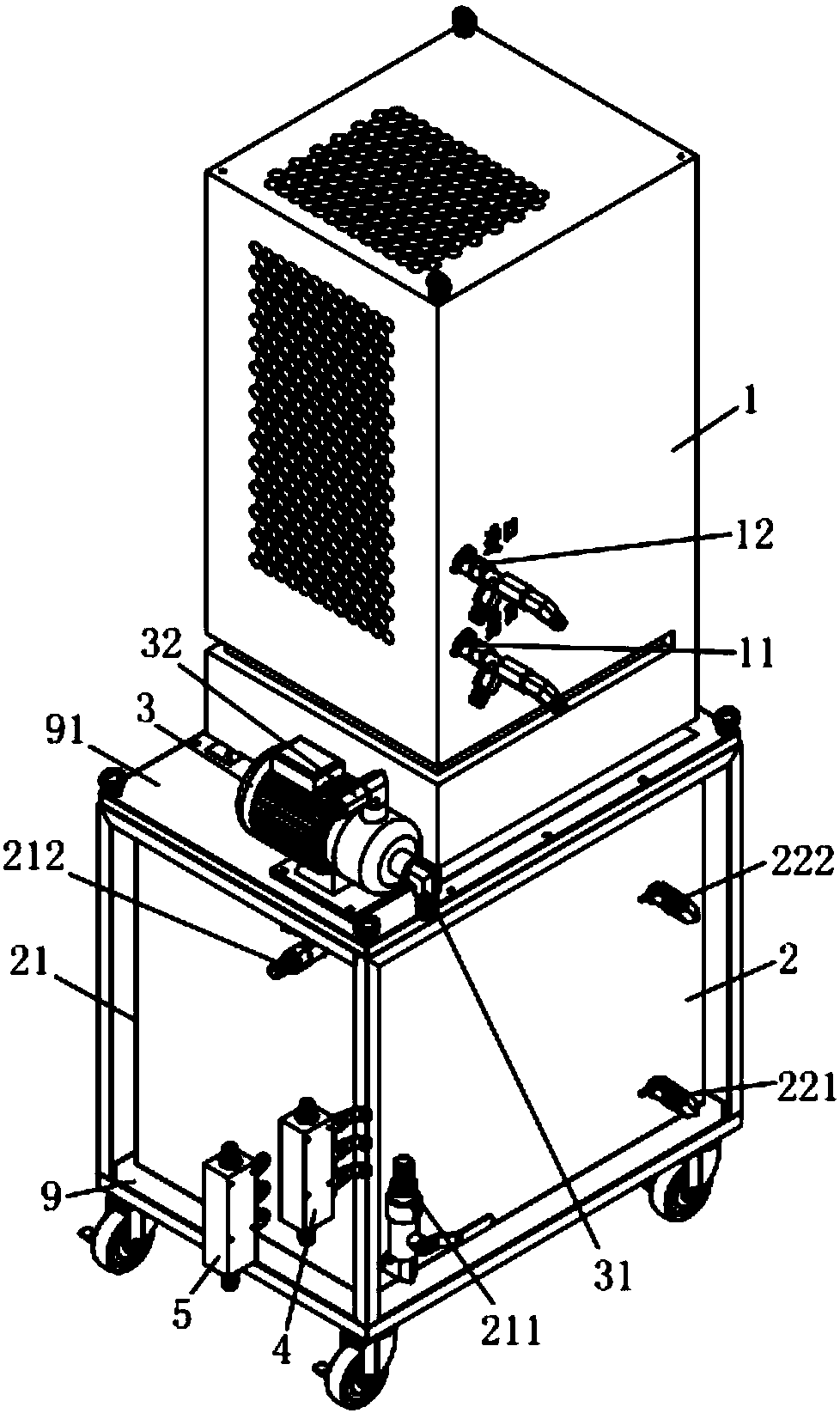
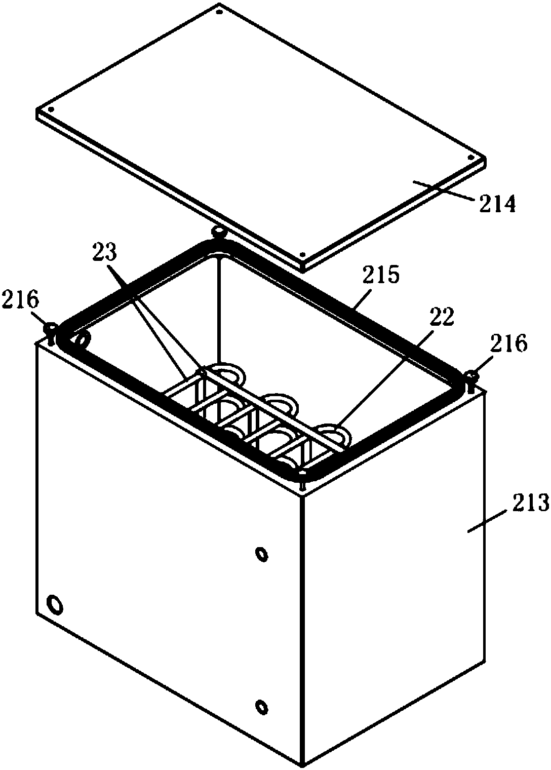
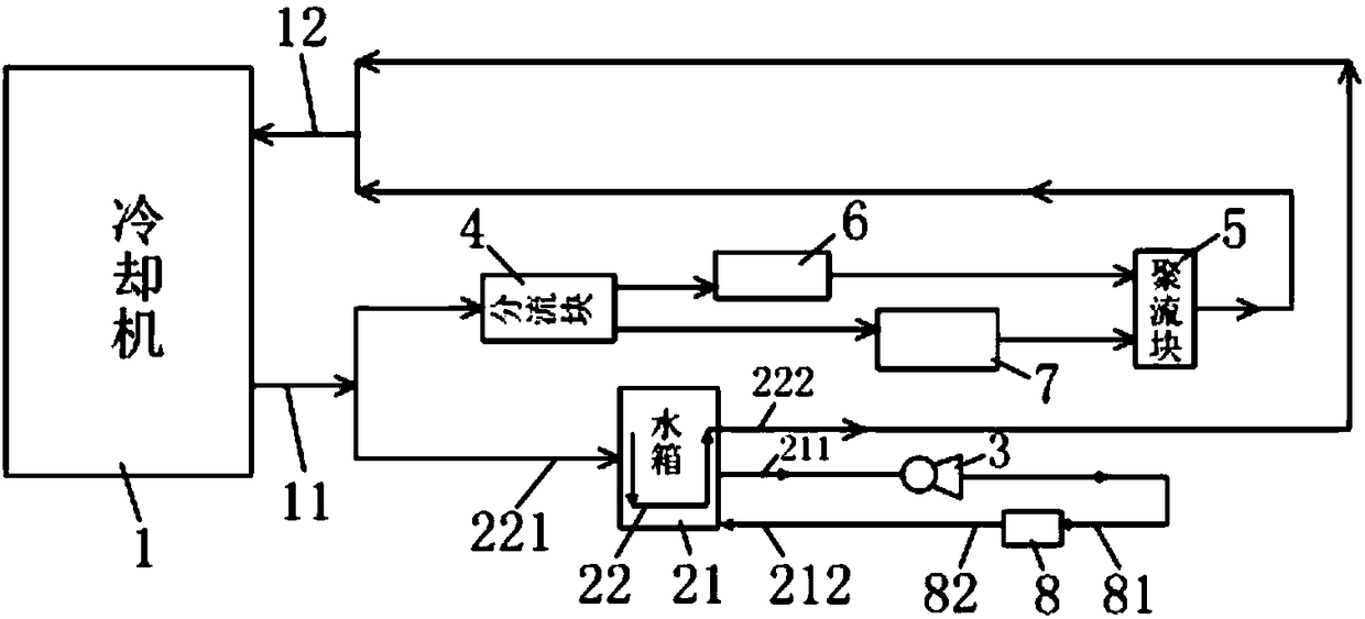
[0034] The constant temperature cooling system of a kind of high-precision numerical control processing machine tool of the present embodiment, such as Figure 1 to Figure 3 As shown, it includes a cooling machine 1, a cooling water tank assembly 2 connected to the cooling machine 1, a water pump 3 connected to the cooling water tank assembly 2, a flow diversion block 4 and a converging block 5 connected to the cooling machine 1; the cooling machine 1 is provided with cooling The liquid outlet 11 and the cooling liquid inlet 12, the cooling liquid outlet 11 and the cooli...


PUM


Abstract

The invention relates to the technical field of numerical control machining, in particular to a constant-temperature cooling system of a high-precision numerical control machining tool. The constant-temperature cooling system comprises a cooler, a cooling water tank assembly, a water pump, a flow dividing block and a flow gathering block, wherein the cooling water tank assembly is connected with the cooler; the water pump is connected with the cooling water tank assembly; the flow dividing block and the flow gathering block are connected with the cooler; the cooler is equipped with a cooling liquid outlet and a cooling liquid inlet; a three-way valve is connected with both the cooling liquid outlet and the cooling liquid inlet; the cooling water tank assembly comprises a water tank and a cooling copper pipe; the water tank is used for accommodating water; the cooling copper pipe is arranged in the water tank; both a copper pipe inlet and a copper pipe outlet of the cooling copper pipeextend out of the water tank; and the water tank is equipped with a water-tank water outlet and a water-tank water inlet. The constant-temperature cooling system of the high-precision numerical control machining tool has the advantages of being low in cost and high in stability, and then the product machining yield can be improved.

Description

technical field [0001] The invention relates to the technical field of numerical control machining, in particular to a constant temperature cooling system of a high-precision numerical control machining machine tool. Background technique [0002] When the CNC machine tool is running, the moving parts of the machine tool will generate heat. The thermal deformation caused by the heat will have a huge impact on the machining accuracy. The heat generated by the operation ensures the machining accuracy. However, in the prior art, the common constant temperature cooling system of CNC machine tools is only equipped with a cooling machine connected to the heat-generating functional parts of the machine tool, but the cooling machine with high precision and high stability is expensive. Although the cooling machine has a completely independent refrigeration system, there is a fatal problem for high-precision and ultra-precision machine tools: when the cooling machine continues to work...

Claims


Application Information

Patent Timeline
Patent Type & Authority Applications(China)
IPC IPC(8): F25D17/02B23Q11/12
CPCF25D17/02B23Q11/127
Inventor 黄光景许建强兰海周陈秋发谢升周
Owner 巨冈精工(广东)股份有限公司
Learn More