
Quakeproof support device for industrial robot

A technology of industrial robots and support devices, applied in manipulators, manufacturing tools, program-controlled manipulators, etc., can solve problems such as position deviation, noise generation, and impact on the working environment, so as to facilitate storage, reduce vibration force, and improve overall temperature resistance. Effect

Inactive Publication Date: 2019-09-24
NANJING YUZHI INTELLIGENT TECH CO LTD
View PDF15 Cites 1 Cited by
  • Summary
  • Abstract
  • Description
  • Claims
  • Application Information

AI Technical Summary

Problems solved by technology

[0005] The purpose of the present invention is to provide an anti-seismic support device for industrial robots to solve the vibrations and noises proposed in the above background technology, which will affect the surrounding working environment, and may also cause position shifts, resulting in industrial processing. There is a deviation that affects the yield of the product

Method used


Image

  • Quakeproof support device for industrial robot
  • Quakeproof support device for industrial robot
  • Quakeproof support device for industrial robot

Examples


Embodiment 1

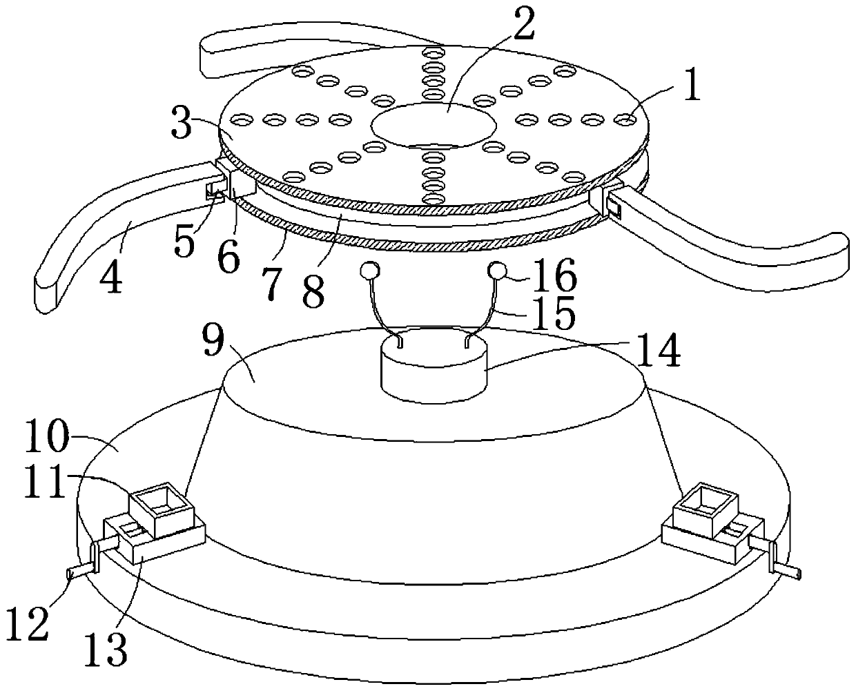
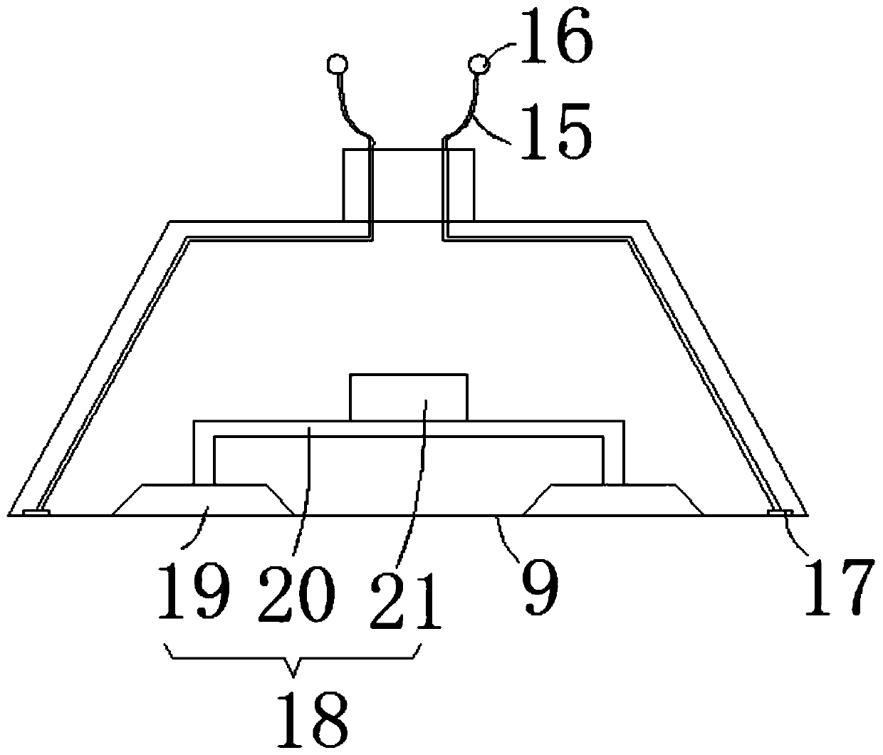
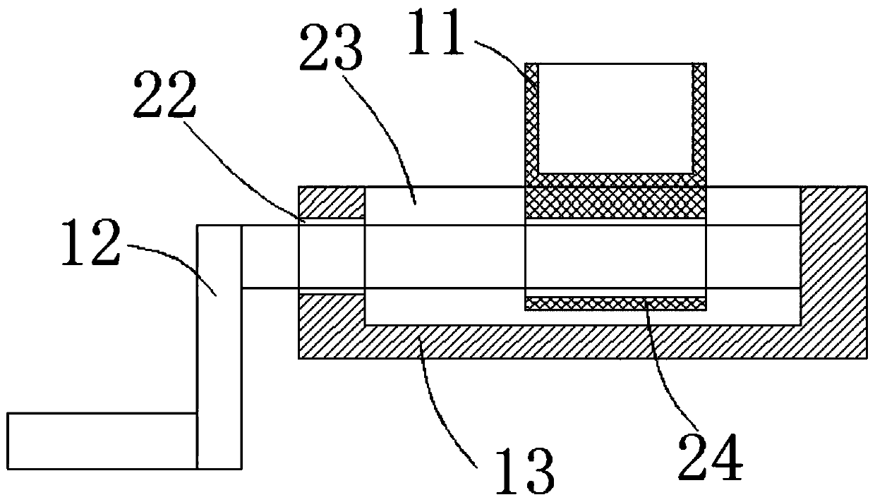
[0026] see Figure 1-4 , the present embodiment provides an anti-seismic support device for industrial robots, including a first support plate 3, a second support plate 7, a rubber seat 9, a chassis 10 and a placement box 11, the first support plate 3 and the second support plate Between the support plates 7, interlayer plates 8 are arranged, and the diameter of the interlayer plates 8 is five-sixths of the diameter of the first support plates 3, and there are three positive and positive joints between the first support plates 3 and the edge positions of the second support plates 7. Triangular distribution of rotating blocks 6, and the side walls of the rotating blocks 6 are not attached to the side walls of the sandwich panel 8, the centers of the side walls of the three rotating blocks 6 are hinged with a rotating block 5, and the three rotating blocks 6 pass through the rotating blocks 5 The support rod 4 is pivotally connected, the center of the first support plate 3, the ...

Embodiment 2

[0029] see Figure 1-4, on the basis of Example 1, a further improvement is made: the first support plate 3 and the second support plate 7 face up and down, and the diameters are equal, and the appearance is beautiful and coordinated. The first support plate 3, the sandwich plate 8 and the second support plate 7 are located on the same central axis, which is convenient for installation. The three support rods 4 are all arc-shaped, and are adapted to the side walls of the interlayer board 8, which is convenient for receiving the support rods 4. The thickness of the three support rods 4 is larger than that of the first support plate 3 and The gap between the second support plate 7 is small 4mm, so that the support rod 4 is convenient to be received in the gap between the first support plate 3 and the second support plate 7, without taking up space, the upper ends of the two conductive strips 15 run through the convex block 14, and is connected with the first metal sheet 16, the ...


PUM


Abstract

The invention discloses a quakeproof support device for an industrial robot. The device comprises a first support plate, a second support plate, a rubber base, a chassis and placing boxes; three turning blocks, distributed in a regular triangle form, are rotationally hinged between the edge positions of the first support plate and the second support plate; rotating blocks are rotationally hinged to the side wall centers of the three turning blocks; the three turning blocks are rotationally hinged with support rods through the rotating blocks; the rubber base is embedded in a placing through hole of the chassis; three adjusting plates, distributed in a regular triangle form, are fixedly welded in the edge position of the top end surface of the chassis; a thread rocking rod penetrates through an adjusting groove, and is rotationally inserted with the back end surface of an inner cavity of the adjusting groove; the thread rocking rod rotationally penetrates through a thread adjusting cylinder through threads; the placing boxes are positioned above the adjusting plates; and the top ends of the three support rods are matched with inner cavities of the three placing boxes. The device conveniently installs the industrial robot, and is high in overall stability, convenient for fine adjustment of the flatness of support planes and convenient to store.

Description

[0001] This patent application is a divisional application. The information of the original application is: application number August 30, 2018, application number 2018110017844, and the title of the invention is a support device for industrial robots. technical field [0002] The invention relates to the related technical field of industrial robot support, in particular to an anti-seismic support device for industrial robots. Background technique [0003] At present, with the rapid development of the industrial economy, more and more advanced technologies are applied to industrial development. In addition, with the advent of high-tech products in emerging industries, that is, the emergence of industrial robots, instead of a large number of labor forces, the The processing accuracy, efficiency, and defective rate are also gradually reduced, which greatly improves the effective utilization of resources and also improves economic benefits. [0004] We know that the precision of...

Claims


Application Information

Patent Timeline
Patent Type & Authority Applications(China)
IPC IPC(8): B25J9/00B25J19/00
CPCB25J9/00B25J9/0009B25J19/00B25J19/0091
Inventor 吴艳
Owner NANJING YUZHI INTELLIGENT TECH CO LTD
Learn More