
Microfluidic device with multiple temperature zones

A technology of temperature zone and temperature control components, applied in the field of active matrix array and its components, can solve the problems of increasing the complexity and cost of the manufacturing process, limiting the range of operation, etc., to promote rapid thermal cycle, reduce time, and reduce the cost of devices cost effect

Active Publication Date: 2018-08-14
SHARP LIFE SCI EU LTD
View PDF20 Cites 11 Cited by
  • Summary
  • Abstract
  • Description
  • Claims
  • Application Information

AI Technical Summary

Problems solved by technology

[0018] However, each of these methods has disadvantages for the above and many other chemical and biochemical manipulations and assays
Disadvantages include: limiting the number of samples that can be processed, limiting the number of heating zones, providing large spacing between heating zones, limiting throughput of samples requiring thermal cycling, providing designs with multiple layers of patterned materials and the multiple Layer patterned materials must be aligned with each other
All of these disadvantages add to the complexity and cost of the manufacturing process and can limit the scope of operation

Method used


Image

  • Microfluidic device with multiple temperature zones
  • Microfluidic device with multiple temperature zones
  • Microfluidic device with multiple temperature zones

Examples


Embodiment 1

[0098] figure 2 with 3(a) An exemplary droplet microfluidic processing system according to the first embodiment of the present invention is shown. The system is divided into two parts, including a box 49 and a reader 40.

[0099] The box body 49 is shown as including the EWOD device 41 and is modularized into, for example, a plastic casing. For example, the module may include an upper plastic part 42 and a lower plastic part 44, although this is a matter of design and many arrangements are possible. Generally, the box 49 includes an input structure 46 (for example, a hole) for inputting fluid, and may optionally include an output structure 48, whereby the liquid can be ejected from the device. The input and output structure is fluidly connected to the fluid gap 35 so that fluid can be input to / output from the EWOD device. EWOD devices generally contain a distribution structure for generating droplets 4 in the fluid gap, for example by electrowetting. Generally, the cassette ca...

no. 2 example

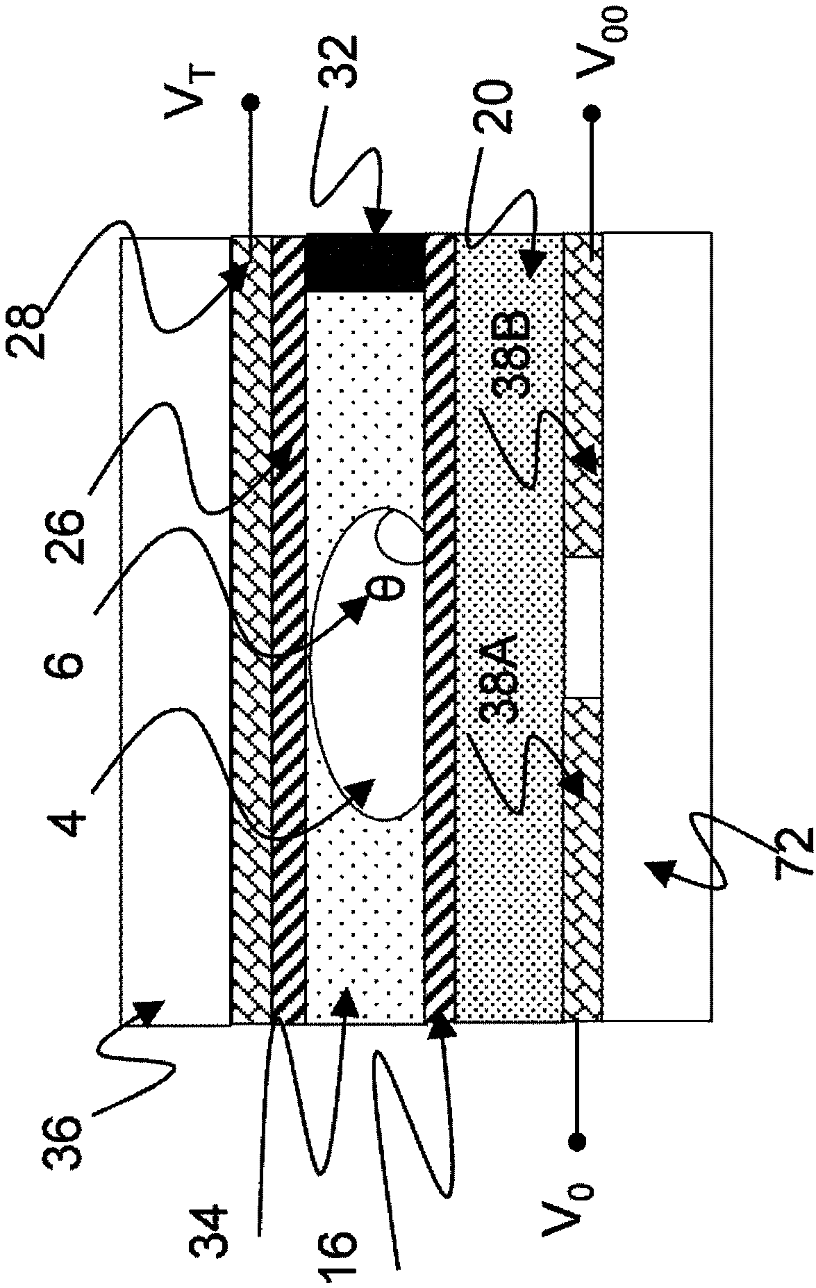
[0137] Figure 5 A second embodiment of the present invention is shown in. The second embodiment is an extension of the first embodiment, in which the internal temperature control elements 52a, 52b of FIG. 3(a) are replaced by external temperature control elements 54a, 54b. These external temperature control elements may be located within the reader 40 or, alternatively, may be fixed to the outer surface of the substrate 36. Similarly, these external temperature control elements 50a, 50b may be located within the reader 40, or alternatively, may be fixed to the outer surface of the lower substrate 72.

[0138] Since the temperature control element is not included in the EWOD device (that is, the temperature control element is included between the upper substrate and the lower substrate), the advantage of this embodiment is that the design of the EWOD device 41 is simplified. In the second embodiment, the temperature control elements of both the upper substrate and the lower subst...

no. 3 example

[0141] Image 6 The third embodiment of the invention shown in is an extension of either of the first or second embodiment, in which an additional temperature control element 56 is provided on the upper substrate 36. The additional temperature control element 56 may be a heat source or a heat sink, and may be controllable independently of the first and second sets of temperature control elements. The purpose of the additional temperature control element is to provide further control over the offset temperature of the device or the temperature of the droplet that is greater or lower than the ambient temperature. This embodiment includes any combination of internal additional temperature control elements and external additional temperature control elements on the upper substrate 36 or the lower substrate 72.

[0142] In this embodiment, as described above, the shape of the temperature distribution created in the fluid gap is still determined by the balance of the heat flow from the...


PUM


Abstract

Disclosed is an EWOD device for processing multiple droplets through multiple temperature zones. The device is configured to achieve a high spatial density of temperature zones with a wide temperaturedifference between hot and cold zones. A first set of temperature control elements is arranged above (or below) a fluid gap in an EWOD device and a second set of temperature control elements is arranged below (or above) the fluid gap. A temperature control element of one set is offset from temperature control elements of the other set in the plane of the fluid gap. The temperature control elementof one set may be located at a different separation from the fluid gap to the temperature control element of the other set. The device has an optional temperature control element and / or arrangement which offsets the low temperature point from the inlet temperature. The two sets of temperature control elements are substantially interacting, in the sense that they cannot be considered to be thermally isolated from one another. This invention also describes methods to process multiple droplets within the multiple temperature zones.

Description

Technical field [0001] The present invention relates to an active matrix array and its components, in particular, to digital microfluidics, and more particularly, to an active matrix electrowetting on dielectric (AM-EWOD) device and a method of driving such a device. The present invention also relates to an AM-EWOD device having a plurality of temperature zones and a method of using these zones to control the temperature of a fluid in the device, wherein the plurality of temperature zones are spatially distributed on the device. Background technique [0002] Electrowetting on Dielectric (EWOD) is a well-known technique for manipulating liquid droplets by applying an electric field. Active matrix EWOD (AM-EWOD) refers to, for example, realizing EWOD in an active matrix array containing transistors by using thin film transistors (TFT). Therefore, EWOD (or AM-EWOD) is a candidate technology for digital microfluidics for laboratory-on-chip technology. An introduction to the basic p...

Claims


Application Information

Patent Timeline
Patent Type & Authority Applications(China)
IPC IPC(8): B01L3/00B01L7/00
CPCB01L3/502784B01L7/525B01L2300/1827B01L2300/1822B01L2300/1811B01L2300/1816B01L3/502707B01L7/54B01L2300/0645B01L2300/0816B01L2300/089B01L2300/1805B01L2300/1861B01L2400/0427B01L3/502792B01L3/50851B01L3/502715B01L3/50273B01L2300/0887B01L2300/18B01L2300/1894G01N27/44704G01N27/44708G01N27/44791G05D23/19
Inventor 菲利浦·马克·施赖恩·罗伯斯帕梅拉·安·多希本杰明·詹姆斯·哈德文
Owner SHARP LIFE SCI EU LTD
Learn More