
Chipping blowing device for machine tool workpieces

A workpiece and chip technology, applied in the field of machine tool processing auxiliary equipment, can solve problems such as adverse effects of mechanical structure movement, damage to parts and circuits, and penetration

Inactive Publication Date: 2018-08-10
贵州龙翔能源(集团)有限公司
View PDF4 Cites 7 Cited by
  • Summary
  • Abstract
  • Description
  • Claims
  • Application Information

AI Technical Summary

Problems solved by technology

[0004] At present, when the machine tool is cutting, drilling, grinding and other processes on the workpiece, debris will be generated. If the debris is not cleaned in time after it is generated, it will easily penetrate into the gaps of the machine tool and become more and more difficult to remove. , and penetration into the machine tool will have an adverse effect on the movement of the mechanical structure, and it is easy to cause damage to parts and circuits. Therefore, it is necessary to design a device that can effectively remove machine tool debris

Method used


Image

  • Chipping blowing device for machine tool workpieces
  • Chipping blowing device for machine tool workpieces
  • Chipping blowing device for machine tool workpieces

Examples


Embodiment Construction

[0027] Below in conjunction with accompanying drawing and embodiment of description, specific embodiment of the present invention is described in further detail:

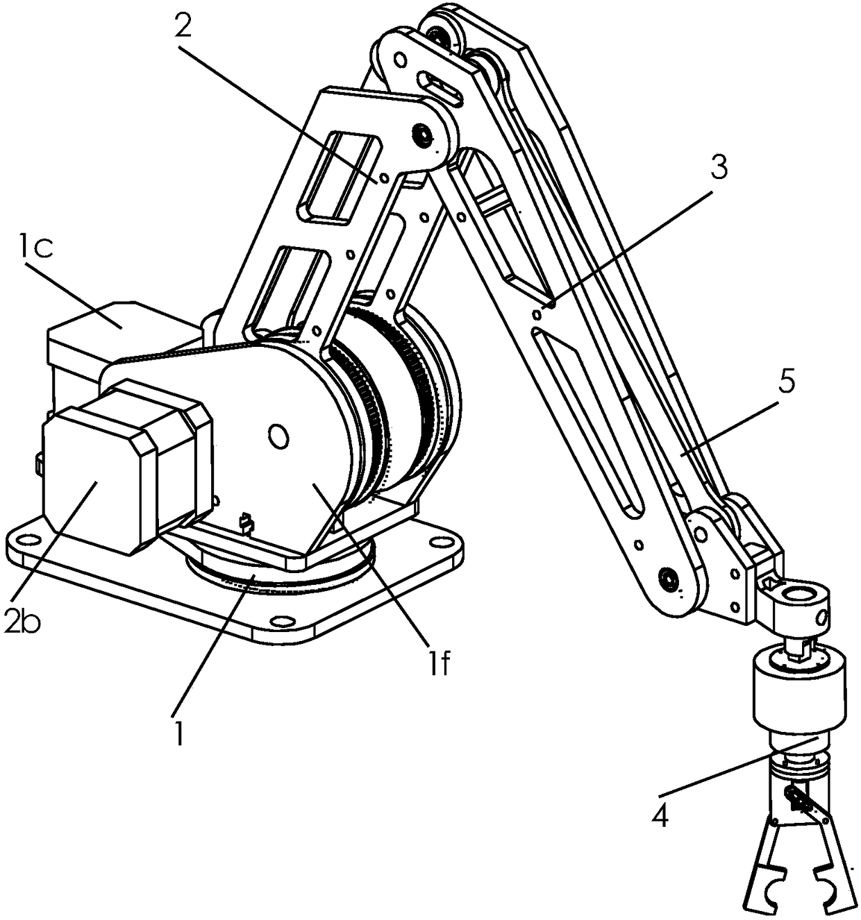
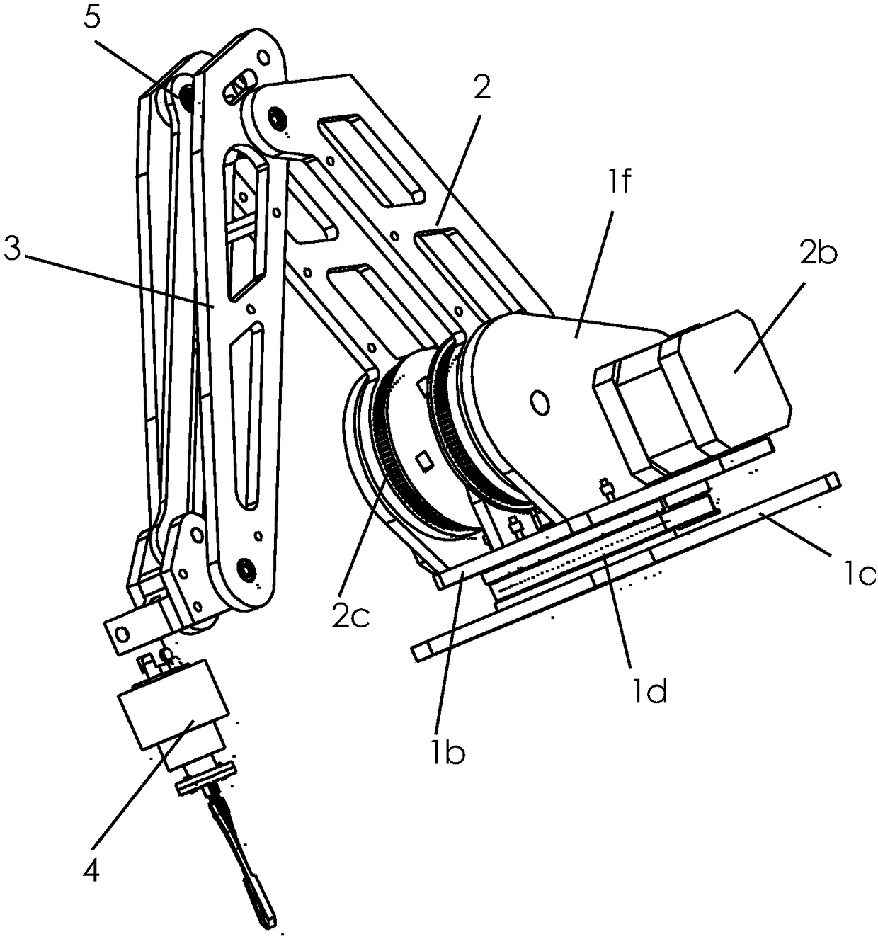
[0028] refer to Figure 1 to Figure 9 The shown device for blowing off debris from machine tool workpieces includes an air pump and an air pipe connected to the air pump, and also includes a rotating base 1 , a mechanical arm 2 , a mechanical arm 3 and a clamping claw 4 .

[0029] The rotating base 1 includes a lower support plate 1a and an upper support plate 1b arranged horizontally, the upper support plate 1b is rotatably arranged above the lower support plate 1a, and one end of the mechanical arm 2 is rotatably arranged on the upper support plate On the top of 1b, the end of the mechanical arm 2 away from the rotating base 1 is hinged to one end of the mechanical arm 3, the clamping claw 4 is rotatably arranged at the non-hinged end of the mechanical arm 3, and the top of the upper support plate 1b is provided w...


PUM


Abstract

The invention relates to the field of machine tool processing auxiliary equipment, and particularly relates to a chipping blowing device for machine tool workpieces. The chipping blowing device comprises an air pump, an air pipe, a rotating base, a mechanical large arm, a mechanical small arm and a clamping jaw, wherein the rotating base comprises a lower support plate and an upper support plate,a first motor is arranged on the top of the upper support plate, an output shaft of the first motor is connected with the rotating base by virtue of a first belt pulley driving mechanism, two second motors are arranged on the top of the upper support plate, the mechanical large arm comprises two first strip-shaped connecting plates, the two first strip-shaped connecting plates are connected with output shafts of the two second motors respectively by virtue of two second belt pulley driving mechanisms, and the clamping jaw is connected with one second belt pulley driving mechanism by virtue ofa horizontal stabilization mechanism. According to the chipping blowing device, the air pipe is clamped by the mechanical arms which can flexibly move and is aligned with a workpiece processing position, and generated chippings are blown away at any time in time, so that the damage caused by chippings to a machine tool is effectively avoided, and the service life of the machine tool is prolonged.

Description

technical field [0001] The invention relates to the field of machine tool processing auxiliary equipment, in particular to a machine tool workpiece chip blowing device. Background technique [0002] A machine tool refers to a machine that manufactures a machine, also known as a machine tool or a tool machine, and is customarily referred to as a machine tool. Generally divided into metal cutting machine tools, forging machine tools and woodworking machine tools, etc., there are many ways to process mechanical parts in modern machinery manufacturing: in addition to cutting, there are casting, forging, welding, stamping, extrusion, etc., but the precision requirements are higher Parts with finer surface roughness requirements generally need to be final processed on machine tools by cutting methods. Machine tools play an important role in the modernization of the national economy. [0003] Machine tool processing refers to the processing of raw materials with machine tools. The...

Claims


Application Information

Patent Timeline
Patent Type & Authority Applications(China)
IPC IPC(8): B23Q11/00
CPCB23Q11/005
Inventor 虞仲华
Owner 贵州龙翔能源(集团)有限公司
Learn More