
Machining center bare machine suitable for multiple environments

A machining center, opto-mechanical technology, applied in metal processing machinery parts, metal processing equipment, manufacturing tools, etc., to achieve the effect of increasing safety and improving market competitiveness

Inactive Publication Date: 2018-08-03
宁波米诺机床有限公司
View PDF5 Cites 8 Cited by
  • Summary
  • Abstract
  • Description
  • Claims
  • Application Information

AI Technical Summary

Problems solved by technology

Optical machine manufacturers need to assemble, inspect, and paint according to relevant international and domestic standards, and then provide assembly to machine tool manufacturers. In the prior art, the optical machine tool holder of the machining center can only move up and down to realize the operation of the spindle. To realize the processing of workpieces, workpieces of different sizes and types require different types of optical machines to assemble machine tools. In view of this, we propose a machining center optical machine that can adapt to various environments

Method used

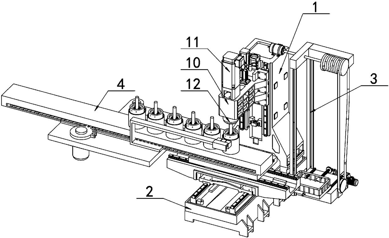
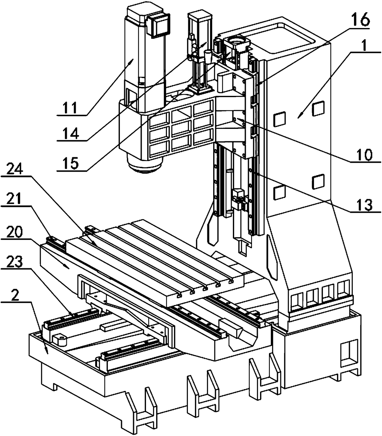
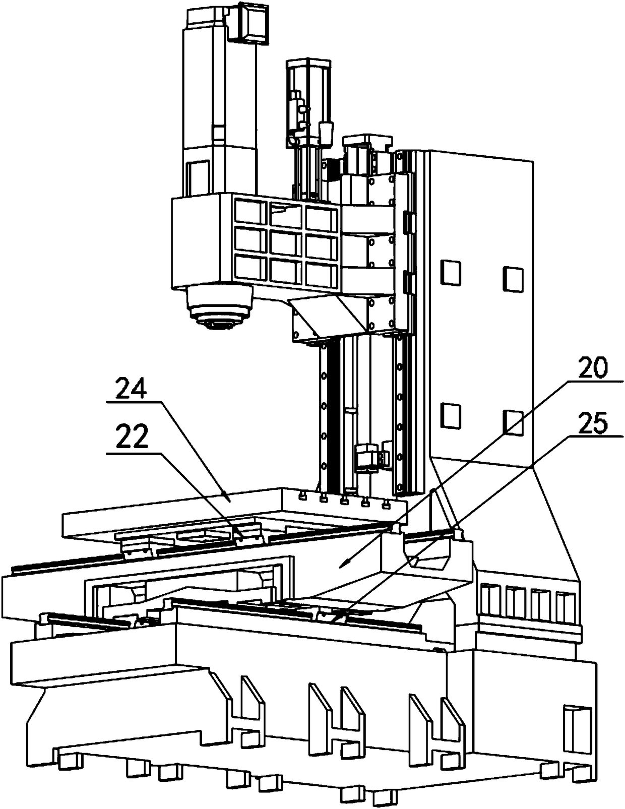

Image

  • Machining center bare machine suitable for multiple environments
  • Machining center bare machine suitable for multiple environments
  • Machining center bare machine suitable for multiple environments

Examples


Embodiment Construction

[0034] The technical solutions in the embodiments of the present invention will be clearly and completely described below in conjunction with the accompanying drawings in the embodiments of the present invention. Obviously, the described embodiments are only a part of the embodiments of the present invention, rather than all the embodiments. Based on the embodiments of the present invention, all other embodiments obtained by those of ordinary skill in the art without creative work shall fall within the protection scope of the present invention.

[0035] See Figure 1-15 , The present invention provides a technical solution:

[0036] A machining center optical engine that can adapt to multiple environments includes an optical engine body 1 and a workbench 2 at the bottom of the optical engine body 1. A tool holder 10 is provided at the front end of the optical engine body 1, and a tool installation is provided at the bottom end of the tool holder 10 Head 12, the top of the tool hol...


PUM


Abstract

The invention relates to the technical field of machine tool equipment, in particular to a machining center bare machine suitable for multiple environments. The machining center bare machine suitablefor multiple environments comprises a bare machine body and a working table arranged at the bottom of the bare machine body. An overhauling mechanism is arranged on one side of the bare machine body.A rapid assembly mechanism is arranged on the other side of the bare machine body. A cutter rest is arranged at the front end of the bare machine body. The bottom end of the cutter rest is provided with a cutter installation head. Through relative sliding between Z-axis rail sliding blocks and Z-axis rails, the cutter rest vertically moves along the Z axis. Through relative sliding between Y-axisrail sliding blocks and Y-axis rails, a saddle and the working table achieve transverse sliding in the Y-axis direction. Through relative sliding between X-axis rail sliding blocks and X-axis rails, atable top and the saddle achieve transverse sliding in the X-axis direction. Through the design of three-dimensional sliding, the bare machine is suitable for machining modes of workpieces of varioussizes in different shapes and suitable for machining in various environments, and therefore the market competitiveness is greatly improved.

Description

Technical field [0001] The invention relates to the technical field of machine tool equipment, in particular to a machining center optical machine that can adapt to multiple environments. Background technique [0002] Machining center machine is composed of the main part and basic parts such as the machine bed, bed saddle, worktable, column, guide rail, head box, etc., and the basic parts of the machine tool, which is the “skeleton” of the machine tool. Hydraulic transmission components, pneumatic components, electric motors and electrical components, as well as components such as numerical control systems. After finishing the assembly, inspection and painting according to relevant international and domestic standards, the machine manufacturer must provide it to the machine tool manufacturer assembly. The tool holder of the machine tool in the existing technology can only move up and down to realize the operation of the spindle To realize the processing of workpieces, different ...

Claims


Application Information

Patent Timeline
Patent Type & Authority Applications(China)
IPC IPC(8): B23Q1/56B23Q1/72B23Q3/155
CPCB23Q1/56B23Q1/72B23Q3/1552B23Q3/15526B23Q3/1554
Inventor 陈文聪徐丽梅金平励波雷冯健
Owner 宁波米诺机床有限公司
Learn More