
Ultra-light special optical cable

An ultra-light and special technology, applied in the direction of light guides, optics, optical components, etc., can solve the problems of inconvenient and fast construction, large bending radius, and large volume, and achieve the advantages of easy transportation and construction, reduced bending radius, and saving storage space Effect

Inactive Publication Date: 2018-07-27
四川六九一二通信技术股份有限公司
View PDF8 Cites 0 Cited by
  • Summary
  • Abstract
  • Description
  • Claims
  • Application Information

AI Technical Summary

Problems solved by technology

This type of armored structure can meet the requirements of tensile and compressive resistance in the field environment to a certain extent, but because it adopts a metal tube or armored structure, it has large volume, heavy weight, and large bending radius, which is not convenient for rapid Inadequacies in construction (such as the construction of communication networks in the battlefield or in the field environment) and other aspects

Method used


Image

  • Ultra-light special optical cable
  • Ultra-light special optical cable
  • Ultra-light special optical cable

Examples


Embodiment 1

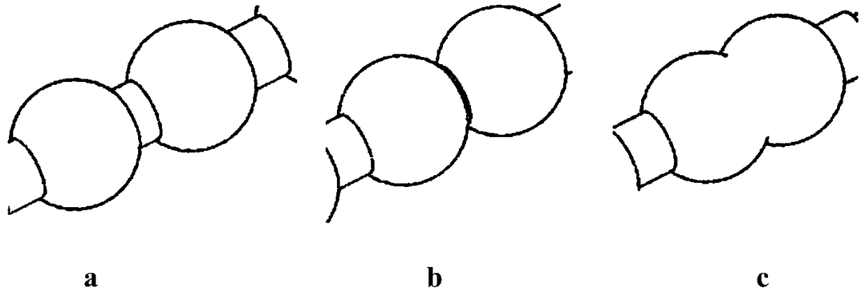
[0027] Such as figure 2 As shown in b, an ultra-light special optical cable includes an outer sheath 1, a tensile layer 2, a compression layer 4 and a fiber core 6 from the outside to the inside, and adjacent layers are arranged in close contact with each other; the outer sheath The thickness of layer 1 is 0.5 mm, and the material used is TPU. The tensile layer 2 is made of Kevlar material. The outer diameter of the compressive layer 4 is 2 mm, which is composed of several tangent spheroids.

Embodiment 2

[0029] Such as figure 2 As shown in c, an ultra-light special optical cable includes an outer sheath 1 from the outside to the inside, a tensile layer 2, a compression layer 4 and a fiber core 6, and adjacent layers are arranged in close contact with each other; the outer sheath The thickness of layer 1 is 0.5 mm, and the material used is TPU. The tensile layer 2 is made of Kevlar material. The outer diameter of the compressive layer 4 is 2 mm, which is composed of several intersecting spheroids.

Embodiment 3

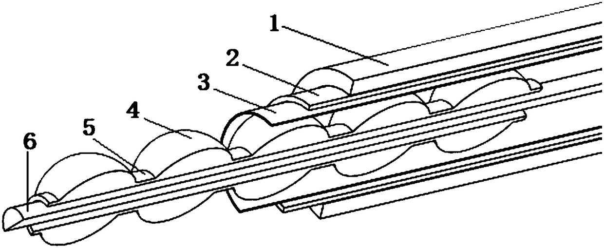
[0031] Such as figure 1 and figure 2 As shown in a, an ultra-light special optical cable includes an outer sheath 1, a tensile layer 2, buffer layers 3, 4 and a fiber core 6 from outside to inside; the thickness of the outer sheath 1 is 1 mm, and the material used It is PE, and the tensile layer 2 is made of aramid fiber. The outer diameter of the compressive layer 4 is 3mm, and it is composed of several spherical bodies separated by a certain distance. Deformed connection part 5, the diameter of the connection part 5 is 2mm, the buffer layer 3 is made of rubber material, and the rubber buffer layer is set to buffer the extrusion between adjacent spheres when the optical cable is bent, and at the same time, it can also reduce the repeated compression of the compression layer. Bending causes abrasion of the tensile layer.


PUM


Abstract

Provided is an ultra-light special optical cable. The cable comprises an outer sheath, a tensile layer, a pressure-resistant layer and a fibre core, and the adjacent layers are closely arranged with each other; the outer sheath has a thickness of 0.1-5 mm, the material used is TPU or PE or PU, the tensile layer is made of aramid or Kevlar, and the outer diameter of the pressure-resistant layer is1.5-5 mm. By changing the structure of the pressure-resistant layer, a discontinuous shape or a notch is made, the bending radius is reduced, the field wiring construction in a wild complex environment can be met, and the contraction between the case that traditional optical cables improve pressure-resistant strength and the case that the traditional optical cables reduce the radius of curvature is solved; the pressure-resistant layer can be made thinner, so that the volume and weight of the cable can be reduced, the cable is convenient to transport and construct, and the storage space can besaved.

Description

technical field [0001] The invention belongs to the technical field of optical cables, and in particular relates to an ultra-light special optical cable. Background technique [0002] With the wide application of communication technology, optical cable, as the core component of information transmission, is used in various communication places such as the Internet and military. For special places such as the field, in order to meet the tensile and compressive strength and other indicators, in the prior art, the structural form of hose or spiral tube or steel mesh or steel wire armor is usually used to protect the fiber core. This type of armored structure can meet the requirements of tensile and compressive resistance in the field environment to a certain extent, but because it adopts metal tube or armored structure, it has large volume, heavy weight, and large bending radius, which is not convenient for rapid Inadequacies in construction (such as the construction of communi...

Claims


Application Information

Patent Timeline
Patent Type & Authority Applications(China)
IPC IPC(8): G02B6/44
CPCG02B6/443G02B6/4427
Inventor 蒋家德姜珂
Owner 四川六九一二通信技术股份有限公司
Learn More