
Three-dimensional electric field and graphene reinforced hollow light-guide fiber photo-catalytic reactor

A technology of photocatalytic reactor and optical fiber, applied in physical/chemical process catalysts, chemical instruments and methods, magnetic/electric field water/sewage treatment, etc., can solve the problem of effective transmission of electron holes and insufficient optical fiber strength, catalyst coating Thickness effect, large light transmission loss and other problems, to achieve the effect of increasing the effective illumination area and photocatalytic reaction area, small reaction specific surface area, and large transmission resistance

Inactive Publication Date: 2018-07-17
徐海澜
View PDF9 Cites 5 Cited by
  • Summary
  • Abstract
  • Description
  • Claims
  • Application Information

AI Technical Summary

Problems solved by technology

[0003] In order to overcome the deficiencies of the existing water, sewage and air purification processes and the application bottleneck of the optical fiber photocatalytic reactor, the invention solves the problem that the light conduction loss in the optical fiber photocatalytic reactor is large, and the thickness of the catalyst coating affects the effective transfer of electron holes. Insufficient optical fiber strength and other problems, increase the effective illumination area and photocatalytic reaction area, thereby improving the reaction efficiency of the optical fiber photocatalytic reactor, and making it possible to increase the length of the optical fiber participating in the effective photocatalytic reaction, which can promote the photoconductive Application of fiber photocatalytic reactor in many fields, especially in the field of environmental engineering

Method used


Image

  • Three-dimensional electric field and graphene reinforced hollow light-guide fiber photo-catalytic reactor
  • Three-dimensional electric field and graphene reinforced hollow light-guide fiber photo-catalytic reactor
  • Three-dimensional electric field and graphene reinforced hollow light-guide fiber photo-catalytic reactor

Examples


Embodiment Construction

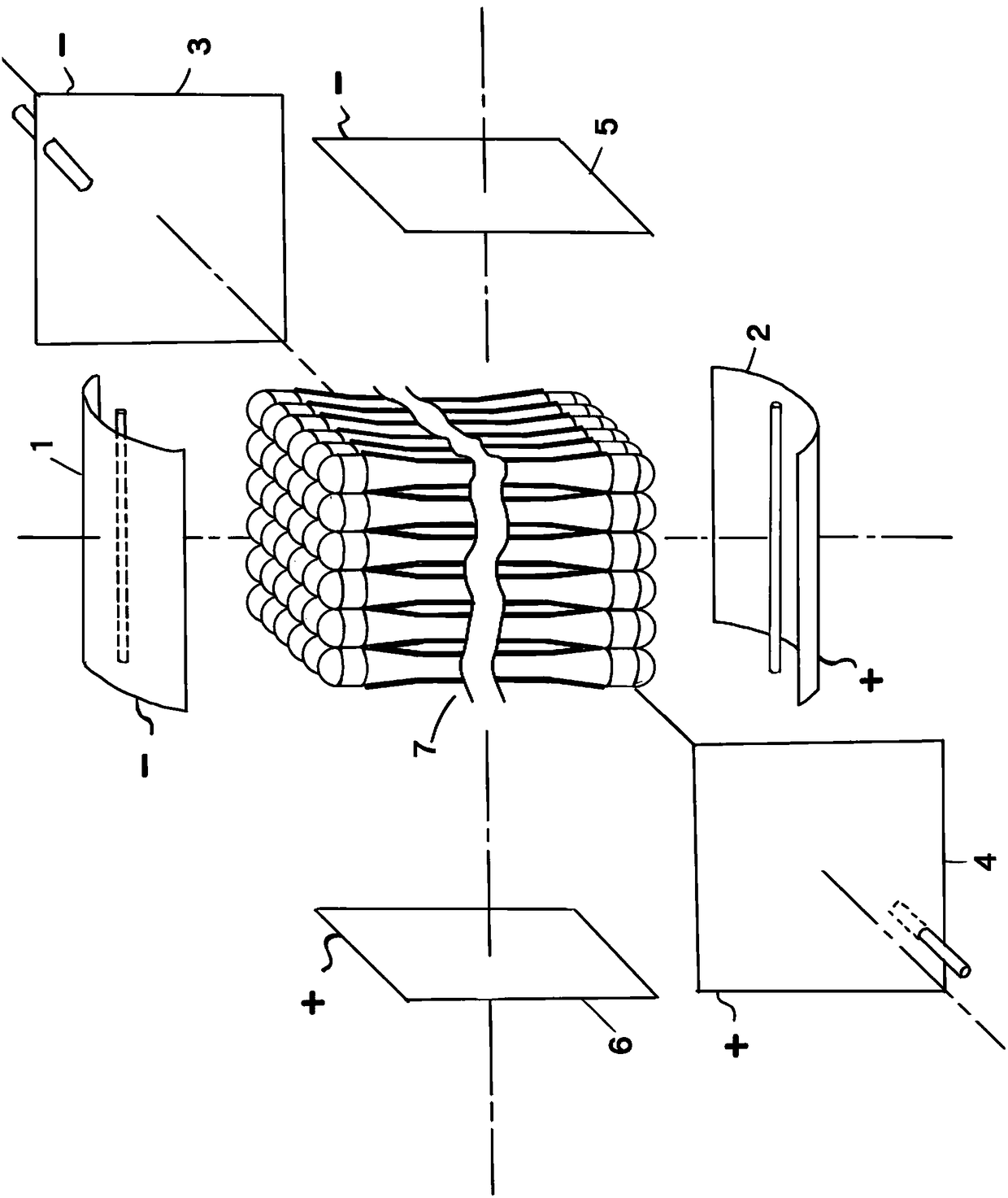
[0016] exist figure 1 Among them, three pairs of electrode plates (1 and 2, 3 and 4, 5 and 6) are placed at positions perpendicular to the three mutually perpendicular symmetry axes, and the pair of electrode plates adjacent to the optical fiber light-introducing end (8) Dome-shaped total reflection mirror metal plates (1 and 2) are used, and ultraviolet lamp tubes are placed at their light reflection focal lengths. The three pairs of electrode plates are alternately fed with low-frequency alternating current below 50 or 60HZ (recommended field strength is 500 to 700 volts), and the power supply is switched to another pair of electrode plates every 0.02 seconds. In the center of the space surrounded by three pairs of electrode plates an assembly (7) is made for a catalyst-coated hollow quartz optical fiber.

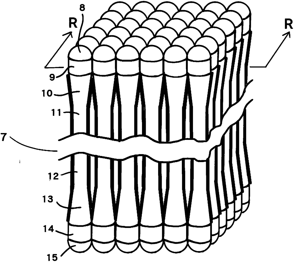
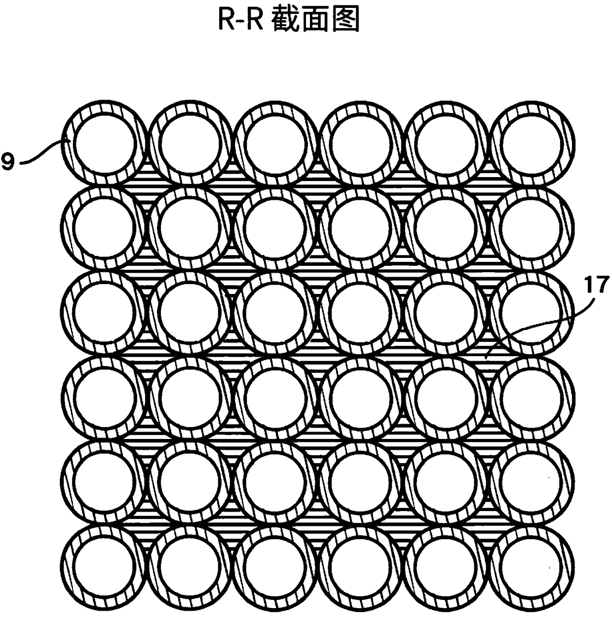
[0017] figure 2 and image 3 respectively figure 1 The enlarged view and R-R cross-sectional view of the hollow quartz optical fiber assembly (7) shown. Figure 4 a...


PUM


Abstract

The invention discloses a three-dimensional electric field and graphene reinforced hollow light-guide fiber photo-catalytic reactor. The photo-catalytic reactor adopts hollow light-guide fibers with convex mirrors at two ends, titanium dioxide and graphene ceramic catalyst coating as well as a three-dimensional low-frequency electric field and a bidirectional light source, so that the catalytic reaction efficiency of the light-guide fiber photo-catalytic reactor is improved. The light-guide fiber photo-catalytic reactor can be applied to purification, disinfection and sterilization of indoor and outdoor air, large-, medium- and small-sized drinking water and swimming pools and various industries as well as agricultural and urban sewage, particularly removal of organic pollutants and bacteria and viruses, disinfection and sterilization of water dispensers to prevent secondary pollution in the drinking water transport and storage process, control of water pollution in rivers, lakes and the sea and degradation of volatile organic compounds and nitric oxides serving as greenhouse gases and haze precursors. The light-guide fiber photo-catalytic reactor can be mounted on small householdair conditioners, large- and medium-sized central air-conditioners, indoor air purifiers, industrial flue gas and exhaust gas emission facilities, small household water purifiers, water dispensers, water works, drinking water supply plants and other water treatment or sewage treatment facilities thereof.

Description

(1) Technical field [0001] The invention relates to a photocatalytic reactor composed of an optical fiber and a photocatalytic film loaded therewith. (2) Background technology [0002] At present, optical fiber photocatalytic reactors have the problems of large loss of light energy in the process of light transmission and the thickness of catalyst coating affecting electron hole transfer, which restricts its application in environmental engineering and chemical engineering. Several recent individual experiments have shown that this set of unresolved issues affects the application of fiber optic photocatalytic reactors. The strength problem of the fiber itself and the problem of large light loss lead to the fiber being easily broken and the light intensity at the far end of the fiber is not enough, resulting in insufficient number of electrons and holes and uneven distribution on the photocatalytic reaction surface. The catalyst coating affects the conduction of electron hol...

Claims


Application Information

Patent Timeline
Patent Type & Authority Applications(China)
IPC IPC(8): B01J19/08B01J19/12C02F9/08B01D53/86B01D53/88B01D53/72B01D53/44B01D53/56B01D53/58B01J21/18
CPCB01D53/007B01D53/32B01D53/8631B01D53/8634B01D53/8668B01D53/8687B01D53/885B01J19/087B01J19/123C02F9/00B01J21/18C02F2101/36C02F2201/3224C02F1/325C02F1/283C02F1/48C02F2305/10C02F2303/04B01D2259/804B01D2258/0266B01D2258/06B01J35/39Y02A20/211Y02A20/212
Inventor 徐文徐海澜
Owner 徐海澜
Learn More