
Double-cavity type impacter with external casing pipe structure

A technology of outer casing and impactor, which is applied in the direction of casing, drill pipe, drilling equipment, etc., can solve the problems of high precision of pin hole processing, difficulty in ensuring matching accuracy, and reduced reliability of impactor, so as to achieve no turning back channel, The air distribution channel is simple and smooth, reducing the effect of energy loss

Pending Publication Date: 2018-06-29
YICHANG WUHUAN ROCK DRILLING TOOLS
View PDF0 Cites 3 Cited by
  • Summary
  • Abstract
  • Description
  • Claims
  • Application Information

AI Technical Summary

Problems solved by technology

[0005] 1. The air distribution rod, the valve seat and the rear joint are rigidly connected by a horizontal pin. The horizontal pin is easily deformed or even broken in the early stage, and the precision of the pin hole matching with the horizontal pin is high, the matching accuracy is not easy to guarantee, and it is inconvenient to install and disassemble
[0006] 3. The air distribution rod is long and has a large air supply hole. It works in a floating way, which is prone to early fracture and reduces the reliability of the impactor when it is working.
[0007] 4. There are more intake and exhaust passages, resulting in greater air pressure loss
[0008] 5. There are many gas distribution channels on the piston, the gas channel turns and the distance is long, and the gas pressure loss is large, which makes it sensitive to heat treatment reaction, stress concentration, and often fails early due to process and structural reasons.

Method used


Image

  • Double-cavity type impacter with external casing pipe structure
  • Double-cavity type impacter with external casing pipe structure
  • Double-cavity type impacter with external casing pipe structure

Examples


Embodiment 1

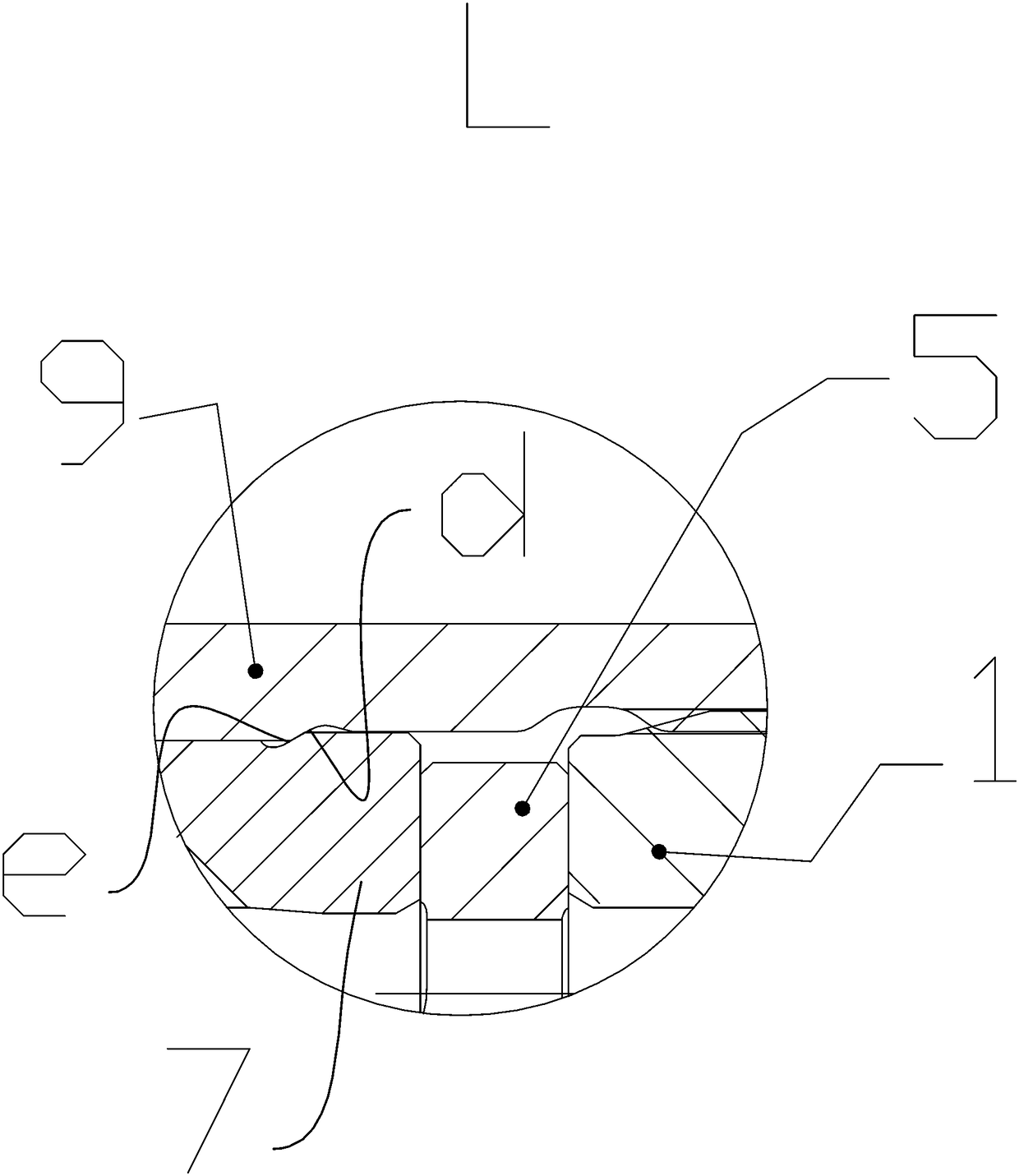
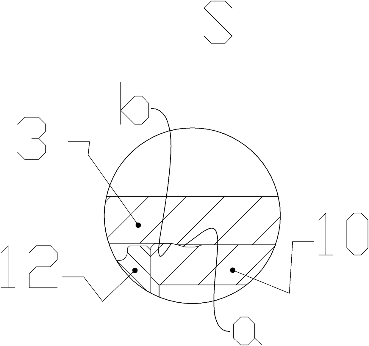
[0047] Such as Figure 1-7 , an impactor with a double-cavity outer sleeve structure, which includes a rear joint 1, an outer sleeve 9 is connected to the rear joint 1; an inner cylinder 7 is set inside the outer sleeve 9, and an inner cylinder 7 of the inner cylinder 7 The interior is positioned by the rear joint 1 and installed with a gas distribution rod 5. A check valve 2 is installed inside the cavity of the gas distribution rod 5, and a spring 4 is installed inside the cavity of the check valve 2; the inside of the outer sleeve 9 Piston 8 is installed, and one end of described piston 8 cooperates with the inner wall of inner cylinder 7, and along with the movement of piston 8, its other end forms sliding fit with the guide sleeve 10 that is installed in outer sleeve 9 inside; The end is equipped with a front joint 13, and a snap ring 12 is installed on the matching end face of the front joint 13 and the guide sleeve 10; the inside of the front joint 13 is fitted with a d...


PUM


Abstract

The invention relates to a double-cavity type impacter with an external casing pipe structure. The double-cavity type impacter comprises a rear joint, and an external casing pipe is connected to the rear joint; an inner cylinder is mounted in the external casing pipe in a sleeved mode, a gas distributing rod is mounted in the inner cylinder through the rear joint in a positioned mode, a check valve is mounted in a cavity of the gas distributing rod, and a spring is mounted in a cavity of the check valve; a piston is mounted in the external casing pipe, one end of the piston is matched with theinner wall of the inner cylinder, and the other end of the piston is matched with a guiding sleeve mounted in the external casing pipe; a front joint is mounted at the tail end of the external casingpipe, and a clamping ring is mounted on the end face, matched with the guiding sleeve, of the front joint in a positioned mode; and a drilling bit is mounted in the front joint through the clamping ring in a limiting sliding fit mode, the impacting end face of the drilling bit is matched with the end face of the piston in a contact mode, and impact energy is transmitted. The working area of the impacting piston is effectively increased, so that the utilization ratio of compressed gas is greatly increased.

Description

technical field [0001] The invention relates to a component of pneumatic impact equipment, in particular to an impactor with a double-cavity outer sleeve structure. Background technique [0002] The valveless down-the-hole hammer is a typical pneumatic impact device. It is the drilling tool of the down-the-hole drilling rig and the working mechanism of the drilling rig for drilling. This equipment is mainly used for drilling blast holes with a diameter of 65-305mm and a hole depth of 60m. Obviously, the drilling efficiency of a down-the-hole drilling rig depends largely on the performance of the impactor. [0003] At present, the valveless down-the-hole impactors used in the market are mainly the Mission series piston-guided sleeve-type valveless single-cylinder structure down-the-hole impactors produced by the Swedish Sandvik Mission Company. The Mission series valveless impactors consist of 16 parts. The rear joint 1 with API thread is the part connecting the impactor an...

Claims


Application Information

Patent Timeline
IPC IPC(8): E21B4/14E21B17/00
CPCE21B4/14E21B17/00
Inventor 龚维龚康强孙超
Owner YICHANG WUHUAN ROCK DRILLING TOOLS
Learn More