
Hydraulically-controlled electronic parking executing mechanism

A technology of electronic parking and actuators, which is applied to vehicle components, brakes, transportation and packaging, etc., can solve the problems of intermittent power transmission, large wear between gears, and large limitations, and achieve continuous power transmission, fewer moving parts, and Applicable to a wide range of car models

Inactive Publication Date: 2012-10-17
NANJING UNIV OF SCI & TECH
View PDF5 Cites 21 Cited by
  • Summary
  • Abstract
  • Description
  • Claims
  • Application Information

AI Technical Summary

Problems solved by technology

[0004] 1. The transmission ratio of the gear mechanism is fixed, and it can only be used one-to-one on the car, which has great limitations
[0005] 2. Since the actuator adopts a gear mechanism, the power transmission will be interrupted and the power will be insufficient.
[0006] Due to the use of mechanical transmission, there are problems of large wear and noise between gears

Method used


Image

  • Hydraulically-controlled electronic parking executing mechanism
  • Hydraulically-controlled electronic parking executing mechanism
  • Hydraulically-controlled electronic parking executing mechanism

Examples


Embodiment Construction

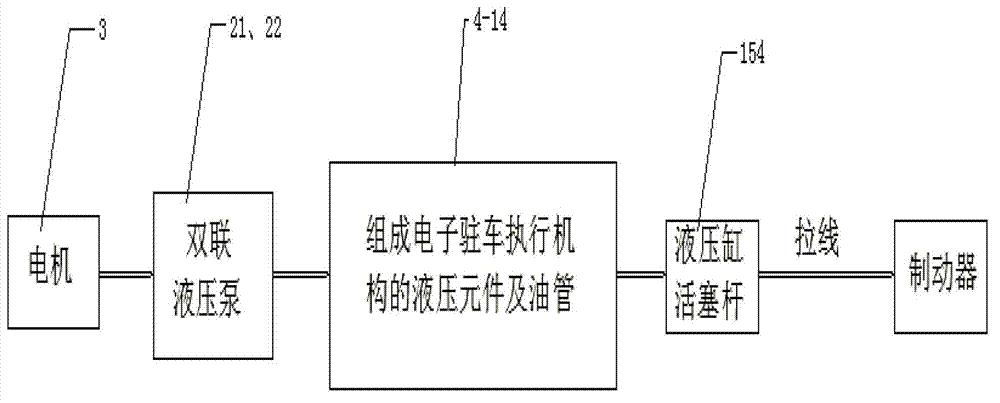
[0022] The general idea of ​​the present invention is as image 3 As shown: the motor 3 controls the double hydraulic pump (high pressure pump 21 and low pressure pump 22) to supply oil to the system, and drives the hydraulic cylinder piston rod 154 through the hydraulic components 4-14 and oil pipes that form the electronic parking actuator, and the piston rod 154 is driven by the piston rod 154 drives the stay wire, controls the brake, and realizes braking.

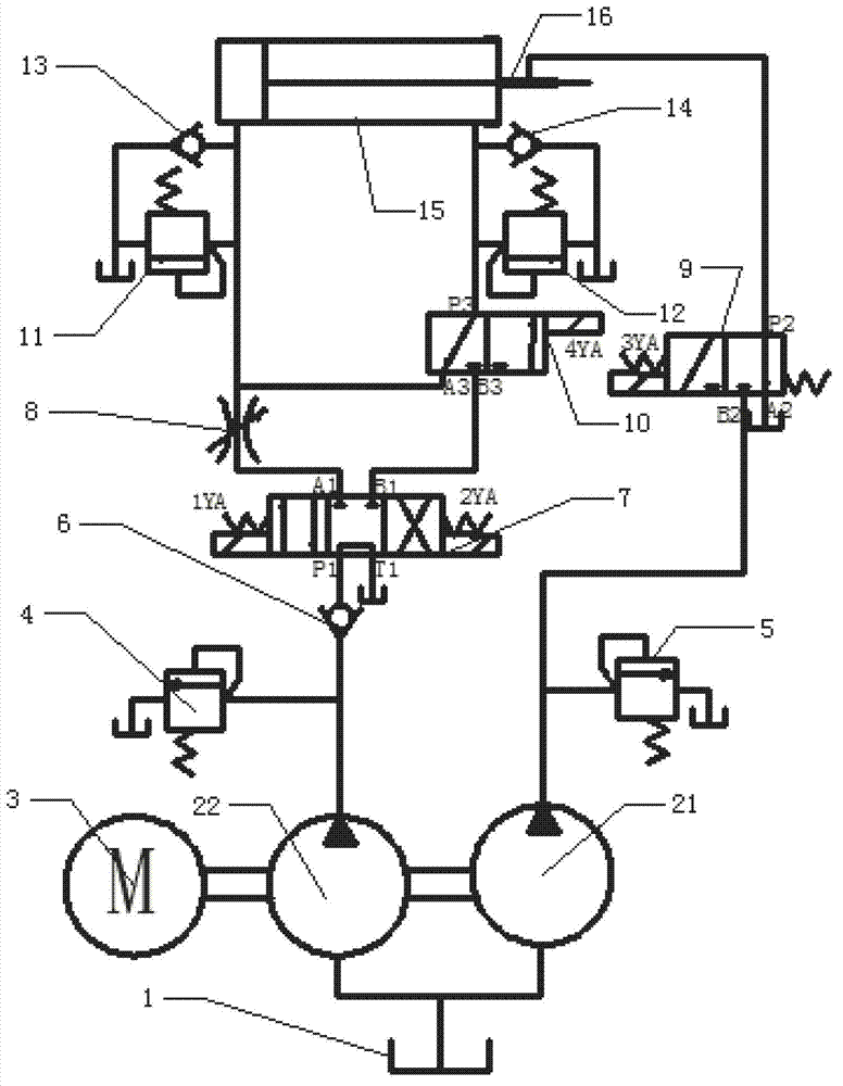
[0023] Such as figure 1 , figure 2 As shown, the hydraulic control electronic parking actuator of the present invention includes a high-pressure pump 21 and a low-pressure pump 22 driven by the motor 3 in double connection, and is used to control the hydraulic cylinder 15 of the brake. The hydraulic cylinder 15 includes a cylinder body 151 located in the cylinder The piston 152 in the body 151, the piston rod 154 connected to one end of the piston 152, and the locking device 16 that is used to lock the piston rod 154...


PUM


Abstract

The invention discloses a hydraulically-controlled electronic parking executing mechanism, which comprises high-pressure and low-pressure pumps driven by using a motor in a duplex way, and a hydraulic cylinder, wherein the hydraulic cylinder comprises a cylinder body, a piston, a piston rod and a locking device; one end of the cylinder body is provided with an oil outlet, and the other end of the cylinder body is provided with an oil inlet; an unlocking oil port is formed at an elastic position on the locking device; the inlet of the high-pressure pump is connected with an oil tank; the port B2 of a first two-position three-way electromagnetic reversing valve is connected with the outlet of the high-pressure pump; the port P2 of the first two-position three-way electromagnetic reversing valve is connected with the unlocking oil port of the locking device; the inlet of the low-pressure pump is connected with the oil tank; the outlet of the low-pressure pump is connected with the port P1 of a three-position four-way electromagnetic reversing valve 7 through a first one-way valve; the inlet of a throttling valve is connected with the port A1 of the three-position four-way electromagnetic reversing valve, and the outlet of the throttling valve is connected with the oil inlet of the cylinder body, so that an oil inlet pipeline is formed; and the port B3 of a second two-position three-way electromagnetic reversing valve is connected with the port B1 of the three-position four-way electromagnetic reversing valve, and the port P3 of the second two-position three-way electromagnetic reversing valve is connected with the oil outlet of the cylinder body, so that an oil outlet pipeline is formed. A braking mechanism disclosed by the invention is suitable for wide vehicle types, and has continuous and stable power transmission, large and adjustable braking force, low wear and low noise.

Description

technical field [0001] The invention belongs to the technical field of vehicle parking brake systems, in particular to a hydraulically controlled electronic parking actuator. Background technique [0002] The current electronic vehicle parking brake method generally uses a gear mechanism to drive to realize the parking brake. The driving actuator is composed of several gears with a fixed number of teeth. Since the number of teeth is fixed, it can provide a stable transmission ratio. The transmitted torque is transmitted to the parking brake of the vehicle through gear transmission, so as to achieve the effect of parking brake. But this device has such a problem, because the number of teeth is fixed, so the transmission ratio that can be provided is fixed, and it cannot meet the changing parking brake requirements, and there will be interruptions in power transmission, insufficient power, etc., which will cause Affects the effect of the parking brake. At the same time, due ...

Claims


Application Information

Patent Timeline
Patent Type & Authority Applications(China)
IPC IPC(8): B60T13/16B60T13/74
Inventor 王显会郑婷王洪亮皮大伟丁义兰吴旭路先锋魏然陆薛松
Owner NANJING UNIV OF SCI & TECH
Learn More