
Ball head milling cutter abrasion detection system and detection method thereof

A ball-end milling cutter and detection system technology, which is applied in the field of physical measurement, can solve problems such as large software and hardware systems, limited measurement objects, and complicated measurement process, and meet the requirements of reducing the positioning accuracy of repeated installation, and the post-analysis is intuitive and clear, reducing the Dangerous effects of winding

Inactive Publication Date: 2018-06-29
HARBIN UNIV OF SCI & TECH
View PDF2 Cites 10 Cited by
  • Summary
  • Abstract
  • Description
  • Claims
  • Application Information

AI Technical Summary

Problems solved by technology

[0003] The existing traditional tool wear detection equipment has a large software and hardware system, which is greatly affected by space conditions. It is often necessary to disassemble the tool, which requires high repeat positioning of the machine tool processing system and low measurement and analysis efficiency. However, the emerging portable detection equipment needs to be fixedly installed with the tool or adjusted to a suitable measurement angle, which is limited by a certain installation space and the geometric shape of the measured object. The measurement process is more complicated, the measurement objects are limited, and the measurement results are in a single form, which is not intuitive enough.

Method used


Image

  • Ball head milling cutter abrasion detection system and detection method thereof
  • Ball head milling cutter abrasion detection system and detection method thereof
  • Ball head milling cutter abrasion detection system and detection method thereof

Examples


Embodiment Construction

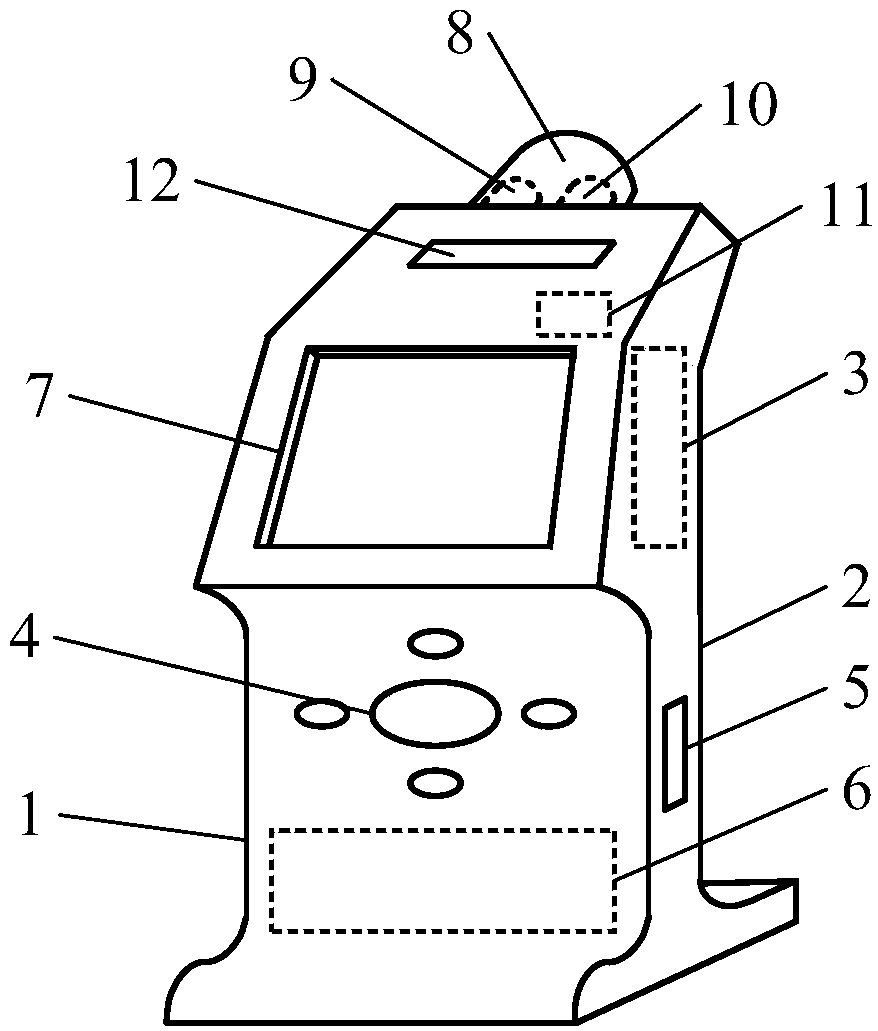
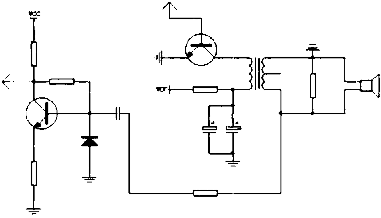
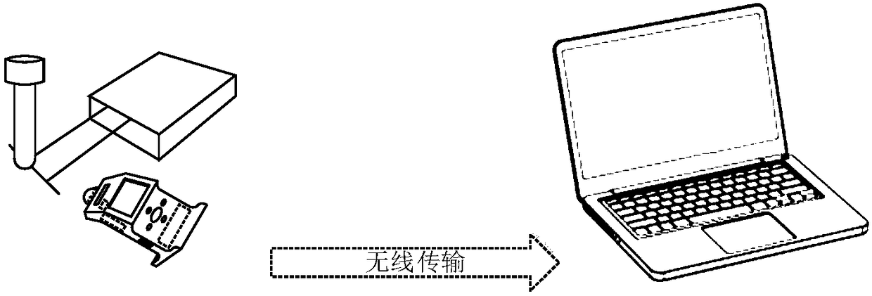
[0022] refer to Figure 1-3 As shown, a ball end milling cutter wear detection system includes a housing 1, a base 2, a circuit board 3, a control room button 4, a data transmission interface 5, a battery compartment 6, a liquid crystal display 7, a detection head 8, and an infrared scanning Head 9, ultrasonic sensor 10, single-chip microcomputer 11 and signal transmitter 12, the liquid crystal display 7 is arranged on the surface of the casing 1, the base 2 is arranged under the casing 1, and the circuit board 3 is arranged in the casing 1 , the circuit board 3 is electrically connected to the liquid crystal display 7, and the base 2 is provided with a data transmission interface 5 and a battery compartment 6. When in use, the measuring head 8 collects data and stores it in the data storage bar. The converted signal is sent by the wireless signal transmitting device 12, and the control button 4 is adjusted so that the circuit board 3 processes and sends the measurement data, ...


PUM


Abstract

The invention discloses a ball head milling cutter abrasion detection system and a detection method thereof. A shell, a base, a circuit board, a control chamber button, a data transmission interface,a battery bin, a liquid crystal display screen, a detection head, an infrared scanning head, an ultrasonic sensor, a single-chip microcomputer and a signal transmitter are included. The liquid crystaldisplay screen is arranged on the surface of the shell, the base is arranged below the shell, and the circuit board is arranged in the shell. The data transmission interface and the battery bin are arranged below the base. The detection head is arranged above the shell and internally provided with the infrared scanning head and the ultrasonic sensor. The detection head is in threaded connection with the shell. A data memory strip and the single-chip microcomputer controlling the ultrasonic sensor are arranged at the bottom of the infrared scanning head. The signal transmitter is arranged above the liquid crystal display screen, and a computer and wireless data receiving equipment which are used in cooperation are additionally arranged. The ball head milling cutter abrasion detection system can directly detect a ball head milling cutter abraded part, and is convenient to operate and high in measuring precision.

Description

technical field [0001] The invention relates to the technical field of physical measurement, in particular to a ball end milling cutter wear detection system and a detection method thereof. Background technique [0002] Ball end milling cutter is a general tool for curved surface processing. It plays a key role in aerospace, vehicles, ships and other important fields related to national economy and people's livelihood. More than 90% of metal processing in industrial production is metal removal processing. With the development of science and technology With the transformation of modern design elements, curved surfaces and streamlined designs are increasingly used in aircraft, vehicles, and ships. Taking steam turbine blades as an example, the most important finishing link in the processing process must use ball end milling cutters. Milling cutters and other cutting tools are the most front-end tools in the manufacturing process, and their own quality is closely related to the...

Claims


Application Information

Patent Timeline
Patent Type & Authority Applications(China)
IPC IPC(8): B23Q17/09B23Q17/00
CPCB23Q17/09B23Q17/00
Inventor 刘献礼赵泽民牛壮张红艳
Owner HARBIN UNIV OF SCI & TECH
Learn More